Commonmark migration
Source Link

Since someone in Bulgaria wanted the same thing for his LED Day Time Running Lights with variable ramp On / Off time , I decided to do a quick design , which is my own invention here for you guys.

It works quite simply by the Relaxation Oscillation like a 555 ( which I have chosen never to use for obscure professional reasons.)

CMOS Schmitt triggers come in various packages with 6 per SOIC14 and have a typical threshold that is used in this design from 1/3 to 2/3 of Vcc. HC14 for 5V logic and others up to 20V logic and Schmitt NAND gates , and works on all the same ( more or less)

I use a 1.5:1 resistor ratio use match this hysteresis range in the DC slew control to frequency delay feedback R of this Relaxation oscillator. This results in disabling the clock then ramping thru 0% to 100% duty cycle and then off again.

If you have any good questions go ahead. Here's my quick and dirty "two-bits" PWM ramp dimmer for any MOSFET driver. It uses the 74HC14 for 5V or the HCF4093 20V CMOS NAND Schmitt trigger if you want to disable with another input.

A PD photo sensor and RC filter with another gate could be used as night sensor with correct bias for light current and cap to avoid transients using a NAND Gate or Inverters.

It was design to turn on the lights after Power On then return to the input logic control state with a ramp time from 0 to 20 seconds using a 1M pot and 10uF Cap.

The delay after switch is a fraction of the total RC time constant which is about half of the 0 to 100% ramp time.

This is not a completed design, just a quick and dirty solution.

The PWM clock actually speeds up in the 1~2 Khz range as it goes thru the 50% PWM zone then slows down at each limit but does not affect the PWM duty cycle.

FALSTAD SIMULATION with manual toggle switch

Enjoy.

[![enter image description here][2]][2]enter image description here
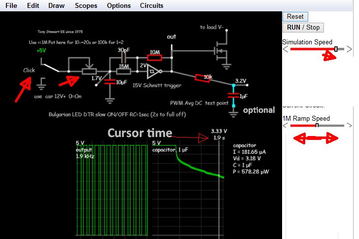
Press Reset top right to start from Time T=0 and adjust slo-mo simulation speed to desired speed and below that adjust pot slide off to ramp speed.

Click switch (left ) to toggle input ( Use another inverting gate ,as this is negative logic)

Also if you want a slight mod makes a manual dinner. For U to figure out . If someone makes a good little PCB, I'll buy it. [2]: https://i.sstatic.net/TMjFh.jpg

Since someone in Bulgaria wanted the same thing for his LED Day Time Running Lights with variable ramp On / Off time , I decided to do a quick design , which is my own invention here for you guys.

It works quite simply by the Relaxation Oscillation like a 555 ( which I have chosen never to use for obscure professional reasons.)

CMOS Schmitt triggers come in various packages with 6 per SOIC14 and have a typical threshold that is used in this design from 1/3 to 2/3 of Vcc. HC14 for 5V logic and others up to 20V logic and Schmitt NAND gates , and works on all the same ( more or less)

I use a 1.5:1 resistor ratio use match this hysteresis range in the DC slew control to frequency delay feedback R of this Relaxation oscillator. This results in disabling the clock then ramping thru 0% to 100% duty cycle and then off again.

If you have any good questions go ahead. Here's my quick and dirty "two-bits" PWM ramp dimmer for any MOSFET driver. It uses the 74HC14 for 5V or the HCF4093 20V CMOS NAND Schmitt trigger if you want to disable with another input.

A PD photo sensor and RC filter with another gate could be used as night sensor with correct bias for light current and cap to avoid transients using a NAND Gate or Inverters.

It was design to turn on the lights after Power On then return to the input logic control state with a ramp time from 0 to 20 seconds using a 1M pot and 10uF Cap.

The delay after switch is a fraction of the total RC time constant which is about half of the 0 to 100% ramp time.

This is not a completed design, just a quick and dirty solution.

The PWM clock actually speeds up in the 1~2 Khz range as it goes thru the 50% PWM zone then slows down at each limit but does not affect the PWM duty cycle.

FALSTAD SIMULATION with manual toggle switch

Enjoy.

[![enter image description here][2]][2]

Press Reset top right to start from Time T=0 and adjust slo-mo simulation speed to desired speed and below that adjust pot slide off to ramp speed.

Click switch (left ) to toggle input ( Use another inverting gate ,as this is negative logic)

Also if you want a slight mod makes a manual dinner. For U to figure out . If someone makes a good little PCB, I'll buy it. [2]: https://i.sstatic.net/TMjFh.jpg

Since someone in Bulgaria wanted the same thing for his LED Day Time Running Lights with variable ramp On / Off time , I decided to do a quick design , which is my own invention here for you guys.

It works quite simply by the Relaxation Oscillation like a 555 ( which I have chosen never to use for obscure professional reasons.)

CMOS Schmitt triggers come in various packages with 6 per SOIC14 and have a typical threshold that is used in this design from 1/3 to 2/3 of Vcc. HC14 for 5V logic and others up to 20V logic and Schmitt NAND gates , and works on all the same ( more or less)

I use a 1.5:1 resistor ratio use match this hysteresis range in the DC slew control to frequency delay feedback R of this Relaxation oscillator. This results in disabling the clock then ramping thru 0% to 100% duty cycle and then off again.

If you have any good questions go ahead. Here's my quick and dirty "two-bits" PWM ramp dimmer for any MOSFET driver. It uses the 74HC14 for 5V or the HCF4093 20V CMOS NAND Schmitt trigger if you want to disable with another input.

A PD photo sensor and RC filter with another gate could be used as night sensor with correct bias for light current and cap to avoid transients using a NAND Gate or Inverters.

It was design to turn on the lights after Power On then return to the input logic control state with a ramp time from 0 to 20 seconds using a 1M pot and 10uF Cap.

The delay after switch is a fraction of the total RC time constant which is about half of the 0 to 100% ramp time.

This is not a completed design, just a quick and dirty solution.

The PWM clock actually speeds up in the 1~2 Khz range as it goes thru the 50% PWM zone then slows down at each limit but does not affect the PWM duty cycle.

FALSTAD SIMULATION with manual toggle switch

Enjoy.

enter image description here

Press Reset top right to start from Time T=0 and adjust slo-mo simulation speed to desired speed and below that adjust pot slide off to ramp speed.

Click switch (left ) to toggle input ( Use another inverting gate ,as this is negative logic)

Also if you want a slight mod makes a manual dinner. For U to figure out . If someone makes a good little PCB, I'll buy it.

added 127 characters in body
Source Link
D.A.S.
  • 148k
  • 3
  • 56
  • 190

Since someone in Bulgaria wanted the same thing for his LED Day Time Running Lights with variable ramp On / Off time , I decided to do a quick design , which is my own invention here for you guys.

It works quite simply by the Relaxation Oscillation like a 555 ( which I have chosen never to use for obscure professional reasons.)

CMOS Schmitt triggers come in various packages with 6 per SOIC14 and have a typical threshold that is used in this design from 1/3 to 2/3 of Vcc. HC14 for 5V logic and others up to 20V logic and Schmitt NAND gates , and works on all the same ( more or less)

I use a 1.5:1 resistor ratio use match this hysteresis range in the DC slew control to frequency delay feedback R of this Relaxation oscillator. This results in disabling the clock then ramping thru 0% to 100% duty cycle and then off again.

If you have any good questions go ahead. Here's my quick and dirty "two-bits" PWM ramp dimmer for any MOSFET driver. It uses the 74HC14 for 5V or the HCF4093 20V CMOS NAND Schmitt trigger if you want to disable with another input.

A PD photo sensor and RC filter with another gate could be used as night sensor with correct bias for light current and cap to avoid transients using a NAND Gate or Inverters.

It was design to turn on the lights after Power On then return to the input logic control state with a ramp time from 0 to 20 seconds using a 1M pot and 10uF Cap.

The delay after switch is a fraction of the total RC time constant which is about half of the 0 to 100% ramp time.

This is not a completed design, just a quick and dirty solution.

The PWM clock actually speeds up in the 1~2 Khz range as it goes thru the 50% PWM zone then slows down at each limit but does not affect the PWM duty cycle.

FALSTAD SIMULATION with manual toggle switch

Enjoy.

[![enter image description here][2]][2]

Press Reset top right to start from Time T=0 and adjust slo-mo simulation speed to desired speed and below that adjust pot slide off to ramp speed.

Click switch (left ) to toggle input ( Use another inverting gate ,as this is negative logic)

Also if you want a slight mod makes a manual dinner. For U to figure out . If someone makes a good little PCB, I'll buy it. [2]: https://i.sstatic.net/TMjFh.jpg

Since someone in Bulgaria wanted the same thing for his LED Day Time Running Lights with variable ramp On / Off time , I decided to do a quick design , which is my own invention here for you guys.

It works quite simply by the Relaxation Oscillation like a 555 ( which I have chosen never to use for obscure professional reasons.)

CMOS Schmitt triggers come in various packages with 6 per SOIC14 and have a typical threshold that is used in this design from 1/3 to 2/3 of Vcc. HC14 for 5V logic and others up to 20V logic and Schmitt NAND gates , and works on all the same ( more or less)

I use a 1.5:1 resistor ratio use match this hysteresis range in the DC slew control to frequency delay feedback R of this Relaxation oscillator. This results in disabling the clock then ramping thru 0% to 100% duty cycle and then off again.

If you have any good questions go ahead. Here's my quick and dirty "two-bits" PWM ramp dimmer for any MOSFET driver. It uses the 74HC14 for 5V or the HCF4093 20V CMOS NAND Schmitt trigger if you want to disable with another input.

A PD photo sensor and RC filter with another gate could be used as night sensor with correct bias for light current and cap to avoid transients using a NAND Gate or Inverters.

It was design to turn on the lights after Power On then return to the input logic control state with a ramp time from 0 to 20 seconds using a 1M pot and 10uF Cap.

The delay after switch is a fraction of the total RC time constant which is about half of the 0 to 100% ramp time.

This is not a completed design, just a quick and dirty solution.

The PWM clock actually speeds up in the 1~2 Khz range as it goes thru the 50% PWM zone then slows down at each limit but does not affect the PWM duty cycle.

FALSTAD SIMULATION with manual toggle switch

Enjoy.

[![enter image description here][2]][2]

Press Reset top right to start from Time T=0 and adjust slo-mo simulation speed to desired speed and below that adjust pot slide off to ramp speed.

Click switch (left ) to toggle input ( Use another inverting gate ,as this is negative logic) [2]: https://i.sstatic.net/TMjFh.jpg

Since someone in Bulgaria wanted the same thing for his LED Day Time Running Lights with variable ramp On / Off time , I decided to do a quick design , which is my own invention here for you guys.

It works quite simply by the Relaxation Oscillation like a 555 ( which I have chosen never to use for obscure professional reasons.)

CMOS Schmitt triggers come in various packages with 6 per SOIC14 and have a typical threshold that is used in this design from 1/3 to 2/3 of Vcc. HC14 for 5V logic and others up to 20V logic and Schmitt NAND gates , and works on all the same ( more or less)

I use a 1.5:1 resistor ratio use match this hysteresis range in the DC slew control to frequency delay feedback R of this Relaxation oscillator. This results in disabling the clock then ramping thru 0% to 100% duty cycle and then off again.

If you have any good questions go ahead. Here's my quick and dirty "two-bits" PWM ramp dimmer for any MOSFET driver. It uses the 74HC14 for 5V or the HCF4093 20V CMOS NAND Schmitt trigger if you want to disable with another input.

A PD photo sensor and RC filter with another gate could be used as night sensor with correct bias for light current and cap to avoid transients using a NAND Gate or Inverters.

It was design to turn on the lights after Power On then return to the input logic control state with a ramp time from 0 to 20 seconds using a 1M pot and 10uF Cap.

The delay after switch is a fraction of the total RC time constant which is about half of the 0 to 100% ramp time.

This is not a completed design, just a quick and dirty solution.

The PWM clock actually speeds up in the 1~2 Khz range as it goes thru the 50% PWM zone then slows down at each limit but does not affect the PWM duty cycle.

FALSTAD SIMULATION with manual toggle switch

Enjoy.

[![enter image description here][2]][2]

Press Reset top right to start from Time T=0 and adjust slo-mo simulation speed to desired speed and below that adjust pot slide off to ramp speed.

Click switch (left ) to toggle input ( Use another inverting gate ,as this is negative logic)

Also if you want a slight mod makes a manual dinner. For U to figure out . If someone makes a good little PCB, I'll buy it. [2]: https://i.sstatic.net/TMjFh.jpg

deleted 304 characters in body
Source Link
D.A.S.
  • 148k
  • 3
  • 56
  • 190

Since someone in Bulgaria wanted the same thing for his LED Day Time Running Lights with variable ramp On / Off time , I decided to do a quick design , which is my own invention here for you guys.

It works quite simply by the Relaxation Oscillation like a 555 ( which I have chosen never to use for obscure professional reasons.)

CMOS Schmitt triggers come in various packages with 6 per SOIC14 and have a typical threshold that is used in this design from 1/3 to 2/3 of Vcc. HC14 for 5V logic and others up to 20V logic and Schmitt NAND gates , and works on all the same ( more or less)

I use a 1.5:1 resistor ratio use match this hysteresis range in the DC slew control to frequency delay feedback R of this Relaxation oscillator. This results in disabling the clock then ramping thru 0% to 100% duty cycle and then off again.

If you have any good questions go ahead. Here's my quick and dirty "two-bits" PWM ramp dimmer for any MOSFET driver. It uses the 74HC14 for 5V or the HCF4093 20V CMOS NAND Schmitt trigger if you want to disable with another input.

A PD photo sensor and RC filter with another gate could be used as night sensor with correct bias for light current and cap to avoid transients using a NAND Gate or Inverters.

It was design to turn on the lights after Power On then return to the input logic control state with a ramp time from 0 to 20 seconds using a 1M pot and 10uF Cap.

The delay after switch is a fraction of the total RC time constant which is about half of the 0 to 100% ramp time.

This is not a completed design, just a quick and dirty solution.

The PWM clock actually speeds up in the 1~2 Khz range as it goes thru the 50% PWM zone then slows down at each limit but does not affect the PWM duty cycle.

FALSTAD SIMULATION with manual toggle switchFALSTAD SIMULATION with manual toggle switch

Enjoy.

[![enter image description here][2]][2]

Press Reset top right to start from Time T=0 and adjust slo-mo simulation speed to desired speed and below that adjust pot slide off to ramp speed.

Click switch (left ) to toggle input ( Use another inverting gate ,as this is negative logic) [2]: enter image description herehttps://i.sstatic.net/TMjFh.jpg

Since someone in Bulgaria wanted the same thing for his LED Day Time Running Lights with variable ramp On / Off time , I decided to do a quick design , which is my own invention here for you guys.

It works quite simply by the Relaxation Oscillation like a 555 ( which I have chosen never to use for obscure professional reasons.)

CMOS Schmitt triggers come in various packages with 6 per SOIC14 and have a typical threshold that is used in this design from 1/3 to 2/3 of Vcc. HC14 for 5V logic and others up to 20V logic and Schmitt NAND gates , and works on all the same ( more or less)

I use a 1.5:1 resistor ratio use match this hysteresis range in the DC slew control to frequency delay feedback R of this Relaxation oscillator. This results in disabling the clock then ramping thru 0% to 100% duty cycle and then off again.

If you have any good questions go ahead. Here's my quick and dirty "two-bits" PWM ramp dimmer for any MOSFET driver. It uses the 74HC14 for 5V or the HCF4093 20V CMOS NAND Schmitt trigger if you want to disable with another input.

A PD photo sensor and RC filter with another gate could be used as night sensor with correct bias for light current and cap to avoid transients using a NAND Gate or Inverters.

It was design to turn on the lights after Power On then return to the input logic control state with a ramp time from 0 to 20 seconds using a 1M pot and 10uF Cap.

The delay after switch is a fraction of the total RC time constant which is about half of the 0 to 100% ramp time.

This is not a completed design, just a quick and dirty solution.

The PWM clock actually speeds up in the 1~2 Khz range as it goes thru the 50% PWM zone then slows down at each limit but does not affect the PWM duty cycle.

FALSTAD SIMULATION with manual toggle switch

Enjoy.

enter image description here

Since someone in Bulgaria wanted the same thing for his LED Day Time Running Lights with variable ramp On / Off time , I decided to do a quick design , which is my own invention here for you guys.

It works quite simply by the Relaxation Oscillation like a 555 ( which I have chosen never to use for obscure professional reasons.)

CMOS Schmitt triggers come in various packages with 6 per SOIC14 and have a typical threshold that is used in this design from 1/3 to 2/3 of Vcc. HC14 for 5V logic and others up to 20V logic and Schmitt NAND gates , and works on all the same ( more or less)

I use a 1.5:1 resistor ratio use match this hysteresis range in the DC slew control to frequency delay feedback R of this Relaxation oscillator. This results in disabling the clock then ramping thru 0% to 100% duty cycle and then off again.

If you have any good questions go ahead. Here's my quick and dirty "two-bits" PWM ramp dimmer for any MOSFET driver. It uses the 74HC14 for 5V or the HCF4093 20V CMOS NAND Schmitt trigger if you want to disable with another input.

A PD photo sensor and RC filter with another gate could be used as night sensor with correct bias for light current and cap to avoid transients using a NAND Gate or Inverters.

It was design to turn on the lights after Power On then return to the input logic control state with a ramp time from 0 to 20 seconds using a 1M pot and 10uF Cap.

The delay after switch is a fraction of the total RC time constant which is about half of the 0 to 100% ramp time.

This is not a completed design, just a quick and dirty solution.

The PWM clock actually speeds up in the 1~2 Khz range as it goes thru the 50% PWM zone then slows down at each limit but does not affect the PWM duty cycle.

FALSTAD SIMULATION with manual toggle switch

Enjoy.

[![enter image description here][2]][2]

Press Reset top right to start from Time T=0 and adjust slo-mo simulation speed to desired speed and below that adjust pot slide off to ramp speed.

Click switch (left ) to toggle input ( Use another inverting gate ,as this is negative logic) [2]: https://i.sstatic.net/TMjFh.jpg

Source Link
D.A.S.
  • 148k
  • 3
  • 56
  • 190
Loading