added 226 characters in body
Source Link

I tested an amplifier on a circuit board with a network analyzer. It was tested under input power of -20dBm, which is well within the linear region.The amplifier uses SMA connectors.

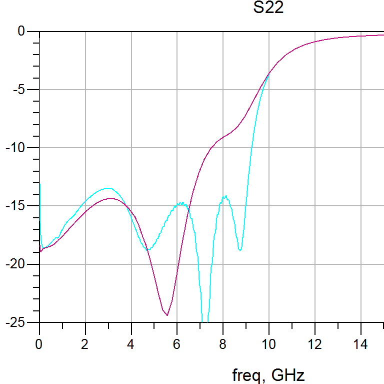
The simulated return loss S22 is smooth, but S22 of the fabricated die shows ripples at round 7GHz. The red trace is from simulation, and blue trace is from measurement.

Do anyone have idea why it might happen? Probably something to do with the RF connectors?

Thanks!!

enter image description here

The simulated return loss S22 is smooth, but S22 of the fabricated die shows ripples at round 7GHz. Do anyone have idea why it might happen? Probably something to do with the RF connectors?

Thanks!!
enter image description here

I tested an amplifier on a circuit board with a network analyzer. It was tested under input power of -20dBm, which is well within the linear region.The amplifier uses SMA connectors.

The simulated return loss S22 is smooth, but S22 of the fabricated die shows ripples at round 7GHz. The red trace is from simulation, and blue trace is from measurement.

Do anyone have idea why it might happen? Probably something to do with the RF connectors?

Thanks!!

enter image description here

Source Link

Why return loss gets ripples?

The simulated return loss S22 is smooth, but S22 of the fabricated die shows ripples at round 7GHz. Do anyone have idea why it might happen? Probably something to do with the RF connectors?

Thanks!!

enter image description here