ADDED:
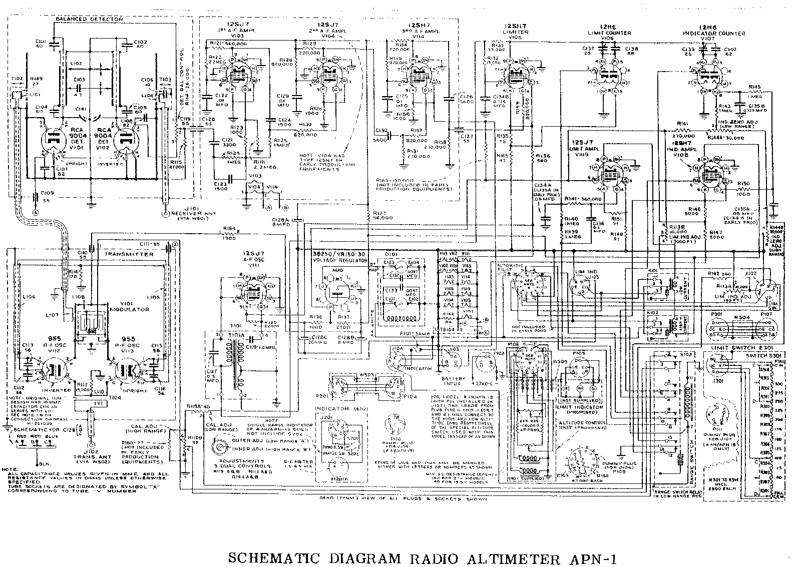
I included the APN1 main circuit diagram as much for fun to show what could be done in 1940 with Acorn tubes BUT in gact it is potentially useful for ideas. The diagram above is readable if you look at it full size as supplied. (Right click and then copy or save or open).This is "as supplied" quality -somebody has scanned the original to a gif in 2 colour "black & white".
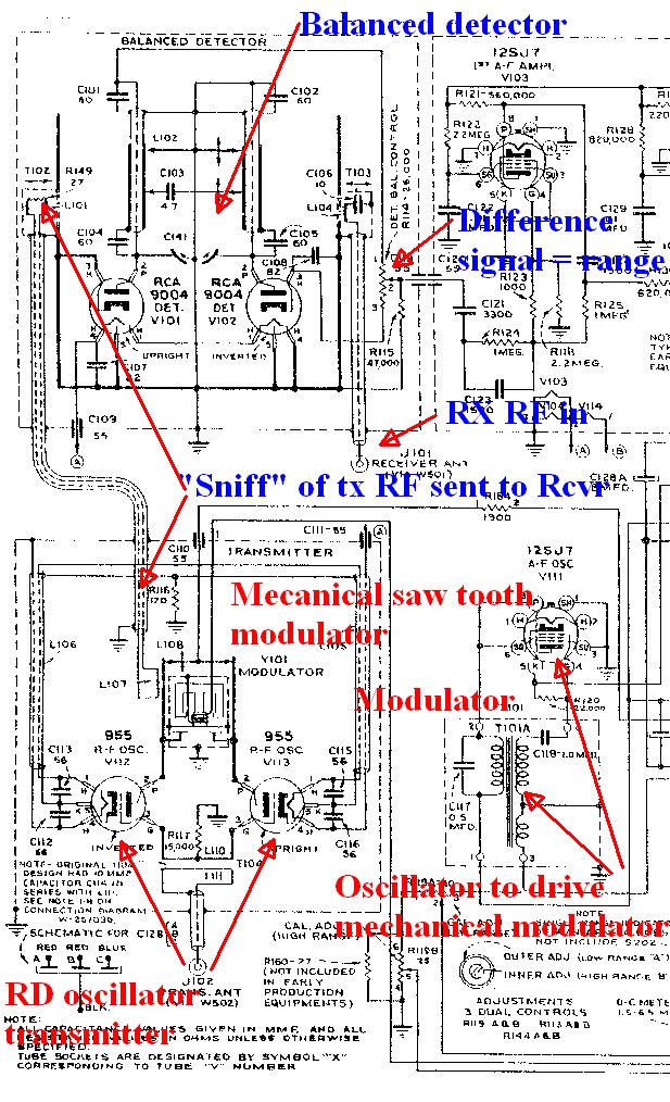
I have copied part of the circuit below and added notes. Something like this could be done with modern components with "relative ease" [tm].
The key special magic is provided by the modulator - here a voice coild driven variable capacitor wihich scans the transmitter across a frequency range. The modern equivalent is a varacror diode - variable capacitance with reverse voltage. The oscillator at right middle drives this modulator.
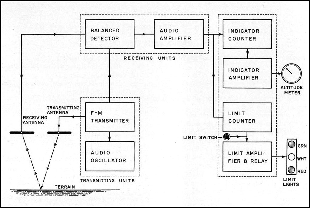
The transmitter is a pair of push-pull acorn tubes driving the transmit aerial at bottom left. A "sniff" [technical term :-) ] of RF is sent from the TX to the RX at top left. A balanced detector - here a pair of Acorn tubes V101 and V102 bu nowadays a Schottky diode ring mixer or similar take the TX sniff and the received echo and mix them to provide a difference signal at the output at top right. This is then amplified as the range signal. Implementing this with "solid state" parts would result in a simple and possibly even effective result. Transmitter beam width would be a major consideration. A GHZ or so oscillator and a lonnnnnng Pringles can antenna (or two) may be enough. Modern cellphone and WiFi components are so readily available (surplus if needs be) that the "hard" RF aspects could be covered by premade parts.


