added 519 characters in body
Source Link
The Photon
  • 133.9k
  • 4
  • 173
  • 319

In your first circuit, so long as the current is small enough and it changes slowly enough, the negative feedback circuit keeps the inverting input of the op-amp at 0 V, so the source sees effectively 0 load impedance.

In the second circuit, the source sees a load impedance equal to the resistor value, which could change the current it produces. Furthermore, the higher the resistance value (increasing the resolution of whatever is measuring the voltage across the resistor), the greater the resistance seen by the source, so the greater the effect on its output.

the "current source seeing some load impedance" [issue]... is a bit confusing since the load resistance will be in series with the current source and why would it have affect on the current. A simple illustration would help a lot if you have time,
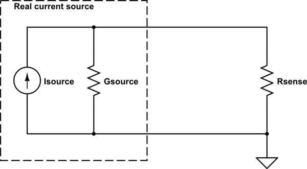
schematic

simulate this circuit – Schematic created using CircuitLab

If Rsense is 0, then all of the source current goes through Rsense and the measurement does not disturb the thing being measured.

If Rsense is non-zero, then some of the source current is diverted internally through the source's internal conductance, and the measured current is lower than it would have been if measured with a 0-resistance sensor.

In your first circuit, so long as the current is small enough and it changes slowly enough, the negative feedback circuit keeps the inverting input of the op-amp at 0 V, so the source sees effectively 0 load impedance.

In the second circuit, the source sees a load impedance equal to the resistor value, which could change the current it produces. Furthermore, the higher the resistance value (increasing the resolution of whatever is measuring the voltage across the resistor), the greater the resistance seen by the source, so the greater the effect on its output.

the "current source seeing some load impedance" [issue]... is a bit confusing since the load resistance will be in series with the current source and why would it have affect on the current. A simple illustration would help a lot if you have time,

schematic

simulate this circuit – Schematic created using CircuitLab

If Rsense is 0, then all of the source current goes through Rsense and the measurement does not disturb the thing being measured.

If Rsense is non-zero, then some of the source current is diverted internally through the source's internal conductance, and the measured current is lower than it would have been if measured with a 0-resistance sensor.

Source Link
The Photon
  • 133.9k
  • 4
  • 173
  • 319

In your first circuit, so long as the current is small enough and it changes slowly enough, the negative feedback circuit keeps the inverting input of the op-amp at 0 V, so the source sees effectively 0 load impedance.

In the second circuit, the source sees a load impedance equal to the resistor value, which could change the current it produces. Furthermore, the higher the resistance value (increasing the resolution of whatever is measuring the voltage across the resistor), the greater the resistance seen by the source, so the greater the effect on its output.