I've built a charger for my 7.2v 3000mAh battery using MAX712 IC.
Here is the datasheet:
http://pdfserv.maximintegrated.com/en/ds/1666.pdf
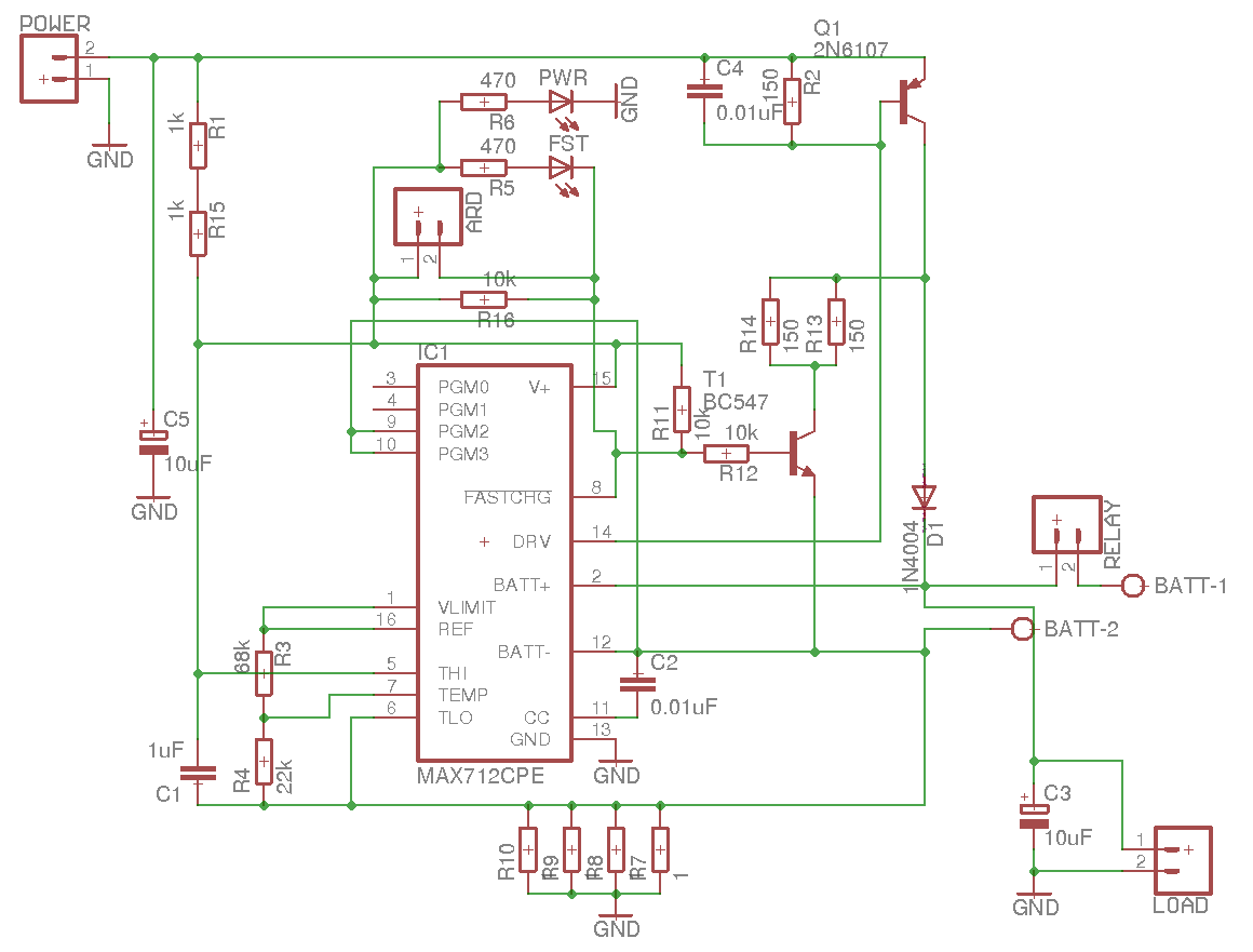
This is the schematic of my charger:
[![enter image description here][1]][1]
It's almost a schematic from datasheet.
Calculations were done with the help of this excellent article:
https://www.rcgroups.com/forums/showthread.php?527385-Building-the-Perfect-Nickel-Chemistry-Charger-Part-II
Here are my values:
- Power source: 15V 3A
- Rsense: 0.25Ohm - 4 1Ohm in parallel.
The IC tries to maintain 0.25V across Rsense(R7,R8,R9,R10 in my schematic), so 0.25R gives (0.25V/0.25R = 1A) of fast charge current.
When I plug the battery in and turn the thing on I get 1A flowing to the battery.
The problem I'm getting is that diode D1 (1N5404 rated 3A - schematic says 1N4004, but I've replaced it on the board) and 2N6107 are getting very hot (can't hold a finger on it for more than a few seconds) on both of them (Q1 even has a heatsink).
According to this formula Q1 should dissipate 9W:
(Q1 pwr dissipation) = [ (DC IN) - (min. battery voltage) ] * (max. charge current) = (15 - 6) * 1 = 9W
The article never mentioned that D1 should be very hot, not any other article I've found, which makes me think something is wrong even though battery gets the correct 1A current.
Any ideas why they might be getting too hot? Any other info I can provide? [1]: https://i.sstatic.net/sbciS.png
