fix typo
Source Link
Dave Tweed
  • 178.3k
  • 17
  • 242
  • 418

This circuit doesn't make sense as shown:

Things to fix:

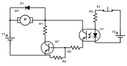
  1. Connect the collector of the opto output to V1+ directly, not to the switched power to the motor. As it is now, the opto turns on Q1, which lowers the voltage on the right side of the motor, which robs power from the opto, which decreases how much Q1 is turned on. That makes no sense, and is probably bad for the motor and Q1.
  2. LooseLose R1. It gets in the way of the motor drawing current. That greatly reduces the motor torque, and causes unnecessary dissipation and wasted power in R1. Connect the right side of the motor directly to the collector of Q1.

This circuit doesn't make sense as shown:

Things to fix:

  1. Connect the collector of the opto output to V1+ directly, not to the switched power to the motor. As it is now, the opto turns on Q1, which lowers the voltage on the right side of the motor, which robs power from the opto, which decreases how much Q1 is turned on. That makes no sense, and is probably bad for the motor and Q1.
  2. Loose R1. It gets in the way of the motor drawing current. That greatly reduces the motor torque, and causes unnecessary dissipation and wasted power in R1. Connect the right side of the motor directly to the collector of Q1.

This circuit doesn't make sense as shown:

Things to fix:

  1. Connect the collector of the opto output to V1+ directly, not to the switched power to the motor. As it is now, the opto turns on Q1, which lowers the voltage on the right side of the motor, which robs power from the opto, which decreases how much Q1 is turned on. That makes no sense, and is probably bad for the motor and Q1.
  2. Lose R1. It gets in the way of the motor drawing current. That greatly reduces the motor torque, and causes unnecessary dissipation and wasted power in R1. Connect the right side of the motor directly to the collector of Q1.
Source Link
Olin Lathrop
  • 315.1k
  • 36
  • 441
  • 928

This circuit doesn't make sense as shown:

Things to fix:

  1. Connect the collector of the opto output to V1+ directly, not to the switched power to the motor. As it is now, the opto turns on Q1, which lowers the voltage on the right side of the motor, which robs power from the opto, which decreases how much Q1 is turned on. That makes no sense, and is probably bad for the motor and Q1.
  2. Loose R1. It gets in the way of the motor drawing current. That greatly reduces the motor torque, and causes unnecessary dissipation and wasted power in R1. Connect the right side of the motor directly to the collector of Q1.