Original answer flawed - basically rewrote
Source Link

I believe Kevin White's answer is partially incorrect (asless partially that I origanally thought!, as well as showing N-channel fets). EitherNeither way will work as demonstrated byif the original questiongate is not referenced to the floating sources unless the gates can goto the extremes of the signal (presumably his editbecause of the diodes). Either way will work with that limitation.

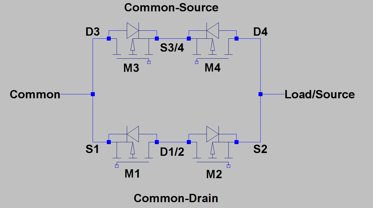
In the common drain the top fet will always turn on first followed by the bottom fetsource case then as Kevin points out referencing the bottom fet's body diode conducts bringing itsgates to the floating source higher than its gate. The issue with this configurationallows switching of positive or negative voltages without limitations of Vgs

enter image description here

If the gates are referenced to the left hand side (Common) then it is clear that itin the Common-Source case if the Load is slower (the upper fet hasmore negative, then Vgate must be < than S3/4 which is only one diode drop from Common to turn on first) and >= Common to turn off. If the supply voltageSource is more positive, then Vgate must be lowerless than max Vgs (strictly speaking V(Gateoff) - V(gnd) < max Vgs)Common to turn on but >= S3/4 which is now one diode drop from Source.

In the common source configurationCommon-Drain case if the upper fet's body diode keepsLoad is more negative, then Vgate must be less than Load to turn on and >= Common to turn off. If the floating sources atSource is more positive, then Vgate must be < 1 diode drop from V(supply) and both fets effectivelyCommon to turn on simultaneouslyand >= Source to turn off.

It isAssuming Common can only swing between Load and Source then Vgate has to be able to swing from Source to Load-G(thres) in either configuration. Apart from possibly the same for Nfact that in the Common-channelDrain case the two fets used ascan share a low-side switch - common source is faster and there isheatsink I can see no Vgs restriction on Vsupplyreason to recommend it.

I believe Kevin White's answer is incorrect (as well as showing N-channel fets). Either way will work as demonstrated by the original question (presumably his edit).

In the common drain the top fet will always turn on first followed by the bottom fet as the bottom fet's body diode conducts bringing its source higher than its gate. The issue with this configuration is that it is slower (the upper fet has to turn on first) and the supply voltage must be lower than max Vgs (strictly speaking V(Gateoff) - V(gnd) < max Vgs).

In the common source configuration the upper fet's body diode keeps the floating sources at < 1 diode drop from V(supply) and both fets effectively turn on simultaneously.

It is the same for N-channel fets used as a low-side switch - common source is faster and there is no Vgs restriction on Vsupply

I believe Kevin White's answer is partially incorrect (less partially that I origanally thought!, as well as showing N-channel fets). Neither way will work if the gate is not referenced to the floating sources unless the gates can goto the extremes of the signal (because of the diodes). Either way will work with that limitation.

In the common source case then as Kevin points out referencing the gates to the floating source allows switching of positive or negative voltages without limitations of Vgs

enter image description here

If the gates are referenced to the left hand side (Common) then it is clear that in the Common-Source case if the Load is more negative, then Vgate must be < than S3/4 which is only one diode drop from Common to turn on and >= Common to turn off. If the Source is more positive, then Vgate must be less than Common to turn on but >= S3/4 which is now one diode drop from Source.

In the Common-Drain case if the Load is more negative, then Vgate must be less than Load to turn on and >= Common to turn off. If the Source is more positive, then Vgate must be < Common to turn on and >= Source to turn off.

Assuming Common can only swing between Load and Source then Vgate has to be able to swing from Source to Load-G(thres) in either configuration. Apart from possibly the fact that in the Common-Drain case the two fets can share a heatsink I can see no reason to recommend it.

Source Link

I believe Kevin White's answer is incorrect (as well as showing N-channel fets). Either way will work as demonstrated by the original question (presumably his edit).

In the common drain the top fet will always turn on first followed by the bottom fet as the bottom fet's body diode conducts bringing its source higher than its gate. The issue with this configuration is that it is slower (the upper fet has to turn on first) and the supply voltage must be lower than max Vgs (strictly speaking V(Gateoff) - V(gnd) < max Vgs).

In the common source configuration the upper fet's body diode keeps the floating sources at < 1 diode drop from V(supply) and both fets effectively turn on simultaneously.

It is the same for N-channel fets used as a low-side switch - common source is faster and there is no Vgs restriction on Vsupply