added 48 characters in body
Source Link
scttnlsn
  • 121
  • 1
  • 5

I'm sending two complementary PWM signals from a control board to a separate power board via a ribbon cable (along with some other signals, 20cm or so). The PWM signals control a MOSFET driver on the power board which, in turn, switch two MOSFETs as part of a half-bridge. I've noticed that as soon as I plug in the PWM signal there's up to ~100mV of noise on the 3.3V rail of the control board (checked with a scope). Since I'm using the 3.3V as a reference for ADC on the control board this is leading to substantial error in the ADC readings.

Is the wiring itself responsible for much of this noise? Wondering if this design is even feasible and whether it would make much difference to move the MCU, etc. from the control board to the power board in order to avoid wiring.

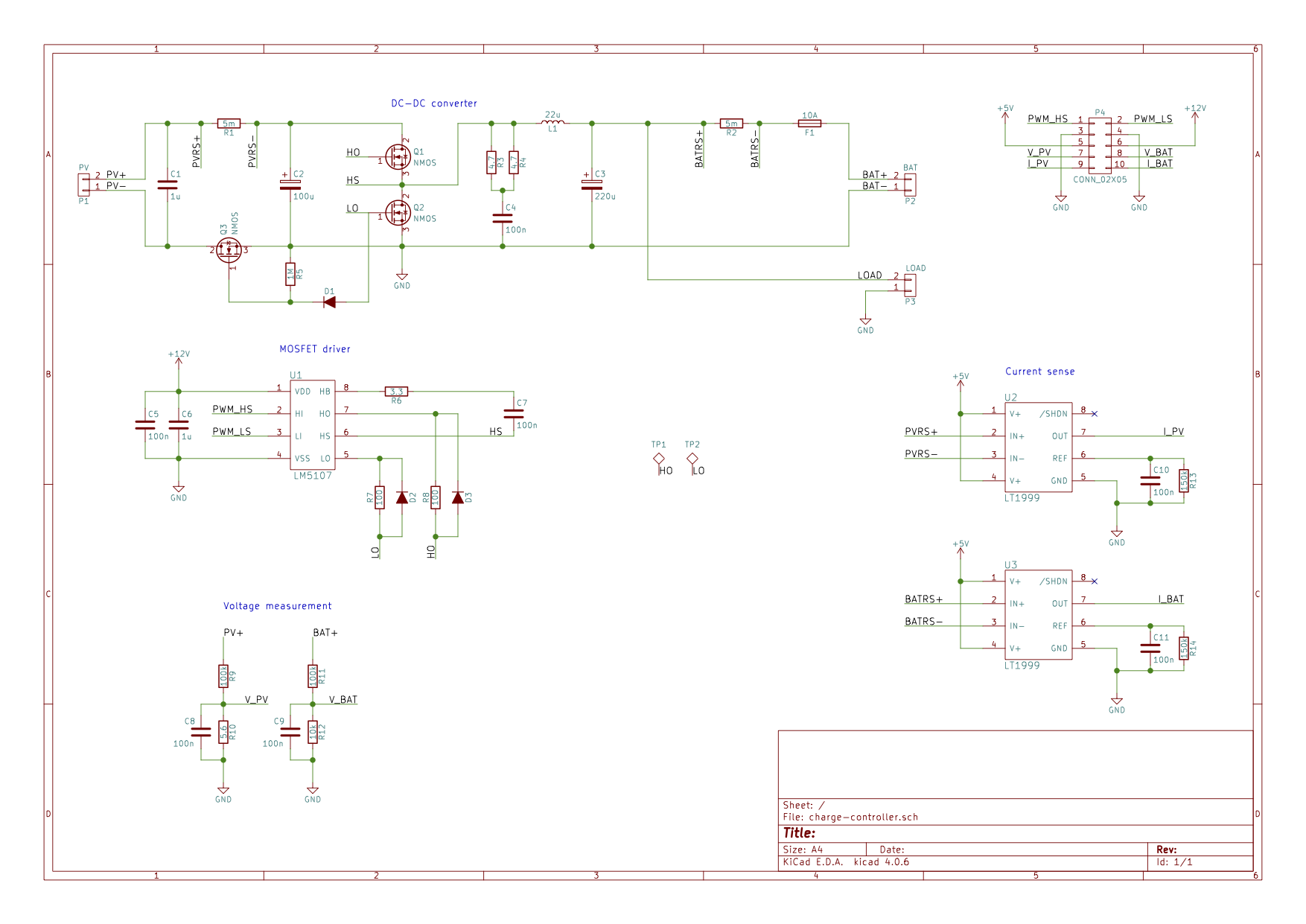
Here's a schematicSchematic of the power board: http://imgur.com/a/62rmP power board schematic
I'm sending two complementary PWM signals from a control board to a separate power board via a ribbon cable (along with some other signals, 20cm or so). The PWM signals control a MOSFET driver on the power board which, in turn, switch two MOSFETs as part of a half-bridge. I've noticed that as soon as I plug in the PWM signal there's up to ~100mV of noise on the 3.3V rail of the control board (checked with a scope). Since I'm using the 3.3V as a reference for ADC on the control board this is leading to substantial error in the ADC readings.

Is the wiring itself responsible for much of this noise? Wondering if this design is even feasible and whether it would make much difference to move the MCU, etc. from the control board to the power board in order to avoid wiring.

Here's a schematic of the power board: http://imgur.com/a/62rmP

I'm sending two complementary PWM signals from a control board to a separate power board via a ribbon cable (along with some other signals, 20cm or so). The PWM signals control a MOSFET driver on the power board which, in turn, switch two MOSFETs as part of a half-bridge. I've noticed that as soon as I plug in the PWM signal there's up to ~100mV of noise on the 3.3V rail of the control board (checked with a scope). Since I'm using the 3.3V as a reference for ADC on the control board this is leading to substantial error in the ADC readings.

Is the wiring itself responsible for much of this noise? Wondering if this design is even feasible and whether it would make much difference to move the MCU, etc. from the control board to the power board in order to avoid wiring.

Schematic of the power board: power board schematic

Added a power board schematic
Source Link
scttnlsn
  • 121
  • 1
  • 5

I'm sending two complementary PWM signals from a control board to a separate power board via a ribbon cable (along with some other signals, 20cm or so). The PWM signals control a MOSFET driver on the power board which, in turn, switch two MOSFETs as part of a half-bridge. I've noticed that as soon as I plug in the PWM signal there's up to ~100mV of noise on the 3.3V rail of the control board (checked with a scope). Since I'm using the 3.3V as a reference for ADC on the control board this is leading to substantial error in the ADC readings.

Is the wiring itself responsible for much of this noise? Wondering if this design is even feasible and whether it would make much difference to move the MCU, etc. from the control board to the power board in order to avoid wiring.

Here's a schematic of the power board: http://imgur.com/a/62rmP

I'm sending two complementary PWM signals from a control board to a separate power board via a ribbon cable (along with some other signals, 20cm or so). The PWM signals control a MOSFET driver on the power board which, in turn, switch two MOSFETs as part of a half-bridge. I've noticed that as soon as I plug in the PWM signal there's up to ~100mV of noise on the 3.3V rail of the control board (checked with a scope). Since I'm using the 3.3V as a reference for ADC on the control board this is leading to substantial error in the ADC readings.

Is the wiring itself responsible for much of this noise? Wondering if this design is even feasible and whether it would make much difference to move the MCU, etc. from the control board to the power board in order to avoid wiring.

Here's a schematic of the power board: http://imgur.com/a/62rmP

Source Link
scttnlsn
  • 121
  • 1
  • 5

Sending PWM signals over wire

I'm sending two complementary PWM signals from a control board to a separate power board via a ribbon cable (along with some other signals, 20cm or so). The PWM signals control a MOSFET driver on the power board which, in turn, switch two MOSFETs as part of a half-bridge. I've noticed that as soon as I plug in the PWM signal there's up to ~100mV of noise on the 3.3V rail of the control board (checked with a scope). Since I'm using the 3.3V as a reference for ADC on the control board this is leading to substantial error in the ADC readings.

Is the wiring itself responsible for much of this noise? Wondering if this design is even feasible and whether it would make much difference to move the MCU, etc. from the control board to the power board in order to avoid wiring.