Notice removed Authoritative reference needed by James
Bounty Ended with Mike DeSimone's answer chosen by James
Added detailed stackup information.
Source Link
James
  • 759
  • 1
  • 9
  • 23

I have a design using an LPC1788 together with a SDRAM module from ISSI (IS42S32800D). This is a 32bit interface.

I have routed this design out and had a prototype made with a PCB manufacturer that does 6 layer prototypes. The prototype PCB works fine. I then thought I would get the PCB manufactured in a small volume batch (100) from my usual PCB supplier. I gave them the stack up information that my prototype used to ensure there would be no issues.

However! I have massive problems with the production board. At first I was unable to raise any response from the SDRAM what-so ever with the same code I used in my prototype board. The previous board was working at 120Mhz so I was sure something was wrong with this new board. I then found a post where people suggested using Repeater Mode on the SDRAM data lines (I had not used this previously) and this raised a response from the SDRAM, however it is not stable. I can write to 16 or so addresses, but then with subsequent reads the data returned (at every address) is the data which I wrote last (probably due to Repeater Mode). When I disable repeater mode, the data returned is 0xFFFFFFF. I am now trying to connect at 48Mhz, the lowest configuration I have timings for.

I am using the same termination resistors (on the Data lines) of 22Ohms on both boards, data lines are an average of 3cm long. Clock line is 2.4cm long. Address lines are average of 3.8cm long.

Is this too out of spec, should I delay the clock longer if it substantially shorter? I am really stuck here, as I have changed nothing about the design I was hoping for a seamless manufacture run for these boards.

Maximum Data Line Length: 59mm (Although this includes the branch to the NAND Flash)
Minimum Data Line Length (Ctrl to Res): 18mm
Maximum Address Line Length: 44mm
Minimum Address Line Length: 24mm
CLK: 24.5mm
CKE: 25mm
CAS: 28mm
RAS: 28.7mm

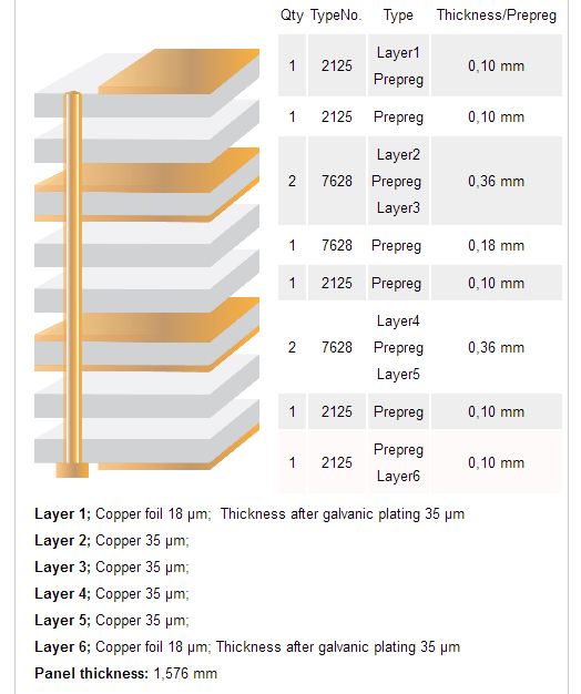
Here is the PCB stack configuration for the original (working) prototype: PCB Stack Configurationenter image description here

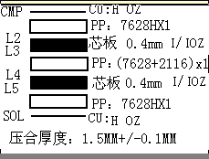
Here is the PCB stack configuration for the production (non-working) PCBs enter image description here

Here is the routing for the SDRAM: SDRAM Routing

I have a design using an LPC1788 together with a SDRAM module from ISSI (IS42S32800D). This is a 32bit interface.

I have routed this design out and had a prototype made with a PCB manufacturer that does 6 layer prototypes. The prototype PCB works fine. I then thought I would get the PCB manufactured in a small volume batch (100) from my usual PCB supplier. I gave them the stack up information that my prototype used to ensure there would be no issues.

However! I have massive problems with the production board. At first I was unable to raise any response from the SDRAM what-so ever with the same code I used in my prototype board. The previous board was working at 120Mhz so I was sure something was wrong with this new board. I then found a post where people suggested using Repeater Mode on the SDRAM data lines (I had not used this previously) and this raised a response from the SDRAM, however it is not stable. I can write to 16 or so addresses, but then with subsequent reads the data returned (at every address) is the data which I wrote last (probably due to Repeater Mode). When I disable repeater mode, the data returned is 0xFFFFFFF. I am now trying to connect at 48Mhz, the lowest configuration I have timings for.

I am using the same termination resistors (on the Data lines) of 22Ohms on both boards, data lines are an average of 3cm long. Clock line is 2.4cm long. Address lines are average of 3.8cm long.

Is this too out of spec, should I delay the clock longer if it substantially shorter? I am really stuck here, as I have changed nothing about the design I was hoping for a seamless manufacture run for these boards.

Maximum Data Line Length: 59mm (Although this includes the branch to the NAND Flash)
Minimum Data Line Length (Ctrl to Res): 18mm
Maximum Address Line Length: 44mm
Minimum Address Line Length: 24mm
CLK: 24.5mm
CKE: 25mm
CAS: 28mm
RAS: 28.7mm

Here is the PCB stack configuration: PCB Stack Configuration

Here is the routing for the SDRAM: SDRAM Routing

I have a design using an LPC1788 together with a SDRAM module from ISSI (IS42S32800D). This is a 32bit interface.

I have routed this design out and had a prototype made with a PCB manufacturer that does 6 layer prototypes. The prototype PCB works fine. I then thought I would get the PCB manufactured in a small volume batch (100) from my usual PCB supplier. I gave them the stack up information that my prototype used to ensure there would be no issues.

However! I have massive problems with the production board. At first I was unable to raise any response from the SDRAM what-so ever with the same code I used in my prototype board. The previous board was working at 120Mhz so I was sure something was wrong with this new board. I then found a post where people suggested using Repeater Mode on the SDRAM data lines (I had not used this previously) and this raised a response from the SDRAM, however it is not stable. I can write to 16 or so addresses, but then with subsequent reads the data returned (at every address) is the data which I wrote last (probably due to Repeater Mode). When I disable repeater mode, the data returned is 0xFFFFFFF. I am now trying to connect at 48Mhz, the lowest configuration I have timings for.

I am using the same termination resistors (on the Data lines) of 22Ohms on both boards, data lines are an average of 3cm long. Clock line is 2.4cm long. Address lines are average of 3.8cm long.

Is this too out of spec, should I delay the clock longer if it substantially shorter? I am really stuck here, as I have changed nothing about the design I was hoping for a seamless manufacture run for these boards.

Maximum Data Line Length: 59mm (Although this includes the branch to the NAND Flash)
Minimum Data Line Length (Ctrl to Res): 18mm
Maximum Address Line Length: 44mm
Minimum Address Line Length: 24mm
CLK: 24.5mm
CKE: 25mm
CAS: 28mm
RAS: 28.7mm

Here is the PCB stack configuration for the original (working) prototype: enter image description here
Here is the PCB stack configuration for the production (non-working) PCBs enter image description here
Here is the routing for the SDRAM: SDRAM Routing

Notice added Authoritative reference needed by James
Bounty Started worth 100 reputation by James
Tweeted twitter.com/#!/StackElectronix/status/200046221786755072
Added min and max line lengths.
Source Link
James
  • 759
  • 1
  • 9
  • 23

I have a design using an LPC1788 together with a SDRAM module from ISSI (IS42S32800D). This is a 32bit interface.

I have routed this design out and had a prototype made with a PCB manufacturer that does 6 layer prototypes. The prototype PCB works fine. I then thought I would get the PCB manufactured in a small volume batch (100) from my usual PCB supplier. I gave them the stack up information that my prototype used to ensure there would be no issues.

However! I have massive problems with the production board. At first I was unable to raise any response from the SDRAM what-so ever with the same code I used in my prototype board. The previous board was working at 120Mhz so I was sure something was wrong with this new board. I then found a post where people suggested using Repeater Mode on the SDRAM data lines (I had not used this previously) and this raised a response from the SDRAM, however it is not stable. I can write to 16 or so addresses, but then with subsequent reads the data returned (at every address) is the data which I wrote last (probably due to Repeater Mode). When I disable repeater mode, the data returned is 0xFFFFFFF. I am now trying to connect at 48Mhz, the lowest configuration I have timings for.

I am using the same termination resistors (on the Data lines) of 22Ohms on both boards, data lines are an average of 3cm long. Clock line is 2.4cm long. Address lines are average of 3.8cm long.

Is this too out of spec, should I delay the clock longer if it substantially shorter? I am really stuck here, as I have changed nothing about the design I was hoping for a seamless manufacture run for these boards.

I would appreciate any help from you guys.

Maximum Data Line Length: 59mm (Although this includes the branch to the NAND Flash)
Minimum Data Line Length (Ctrl to Res): 18mm
Maximum Address Line Length: 44mm
Minimum Address Line Length: 24mm
CLK: 24.5mm
CKE: 25mm
CAS: 28mm
RAS: 28.7mm

Here is the PCB stack configuration: PCB Stack Configuration

Here is the routing for the SDRAM: SDRAM Routing

I have a design using an LPC1788 together with a SDRAM module from ISSI (IS42S32800D). This is a 32bit interface.

I have routed this design out and had a prototype made with a PCB manufacturer that does 6 layer prototypes. The prototype PCB works fine. I then thought I would get the PCB manufactured in a small volume batch (100) from my usual PCB supplier. I gave them the stack up information that my prototype used to ensure there would be no issues.

However! I have massive problems with the production board. At first I was unable to raise any response from the SDRAM what-so ever with the same code I used in my prototype board. The previous board was working at 120Mhz so I was sure something was wrong with this new board. I then found a post where people suggested using Repeater Mode on the SDRAM data lines (I had not used this previously) and this raised a response from the SDRAM, however it is not stable. I can write to 16 or so addresses, but then with subsequent reads the data returned (at every address) is the data which I wrote last (probably due to Repeater Mode). When I disable repeater mode, the data returned is 0xFFFFFFF. I am now trying to connect at 48Mhz, the lowest configuration I have timings for.

I am using the same termination resistors (on the Data lines) of 22Ohms on both boards, data lines are an average of 3cm long. Clock line is 2.4cm long. Address lines are average of 3.8cm long.

Is this too out of spec, should I delay the clock longer if it substantially shorter? I am really stuck here, as I have changed nothing about the design I was hoping for a seamless manufacture run for these boards.

I would appreciate any help from you guys.

Here is the PCB stack configuration: PCB Stack Configuration

Here is the routing for the SDRAM: SDRAM Routing

I have a design using an LPC1788 together with a SDRAM module from ISSI (IS42S32800D). This is a 32bit interface.

I have routed this design out and had a prototype made with a PCB manufacturer that does 6 layer prototypes. The prototype PCB works fine. I then thought I would get the PCB manufactured in a small volume batch (100) from my usual PCB supplier. I gave them the stack up information that my prototype used to ensure there would be no issues.

However! I have massive problems with the production board. At first I was unable to raise any response from the SDRAM what-so ever with the same code I used in my prototype board. The previous board was working at 120Mhz so I was sure something was wrong with this new board. I then found a post where people suggested using Repeater Mode on the SDRAM data lines (I had not used this previously) and this raised a response from the SDRAM, however it is not stable. I can write to 16 or so addresses, but then with subsequent reads the data returned (at every address) is the data which I wrote last (probably due to Repeater Mode). When I disable repeater mode, the data returned is 0xFFFFFFF. I am now trying to connect at 48Mhz, the lowest configuration I have timings for.

I am using the same termination resistors (on the Data lines) of 22Ohms on both boards, data lines are an average of 3cm long. Clock line is 2.4cm long. Address lines are average of 3.8cm long.

Is this too out of spec, should I delay the clock longer if it substantially shorter? I am really stuck here, as I have changed nothing about the design I was hoping for a seamless manufacture run for these boards.

Maximum Data Line Length: 59mm (Although this includes the branch to the NAND Flash)
Minimum Data Line Length (Ctrl to Res): 18mm
Maximum Address Line Length: 44mm
Minimum Address Line Length: 24mm
CLK: 24.5mm
CKE: 25mm
CAS: 28mm
RAS: 28.7mm

Here is the PCB stack configuration: PCB Stack Configuration

Here is the routing for the SDRAM: SDRAM Routing

I have a design using an LPC1788LPC1788 together with a SDRAM module from ISSI (IS42S32800DIS42S32800D). This is a 32bit interface.

I have routed this design out and had a prototype made with a PCB manufacturer that does 6 layer prototypes. The prototype PCB works fine. I then thought I would get the PCB manufactured in a small volume batch (100) from my usual PCB supplier. I gave them the stack up information that my prototype used to ensure there would be no issues.

However! I have massive problems with the production board. At first I was unable to raise any response from the SDRAM what-so ever with the same code I used in my prototype board. The previous board was working at 120Mhz so I was sure something was wrong with this new board. I then found a post where people suggested using Repeater Mode on the SDRAM data lines (I had not used this previously) and this raised a response from the SDRAM, however it is not stable. I can write to 16 or so addresses, but then with subsequent reads the data returned (at every address) is the data which I wrote last (probably due to Repeater Mode). When I disable repeater mode, the data returned is 0xFFFFFFF. I am now trying to connect at 48Mhz, the lowest configuration I have timings for.

I am using the same termination resistors (on the Data lines) of 22Ohms on both boards, data lines are an average of 3cm long. Clock line is 2.4cm long. Address lines are average of 3.8cm long.

Is this too out of spec, should I delay the clock longer if it substantially shorter? I am really stuck here, as I have changed nothing about the design I was hoping for a seamless manufacture run for these boards.

I would appreciate any help from you guys.

Here is the PCB stack configuration: PCB Stack Configuration

Here is the routing for the SDRAM: SDRAM Routing

I have a design using an LPC1788 together with a SDRAM module from ISSI (IS42S32800D). This is a 32bit interface.

I have routed this design out and had a prototype made with a PCB manufacturer that does 6 layer prototypes. The prototype PCB works fine. I then thought I would get the PCB manufactured in a small volume batch (100) from my usual PCB supplier. I gave them the stack up information that my prototype used to ensure there would be no issues.

However! I have massive problems with the production board. At first I was unable to raise any response from the SDRAM what-so ever with the same code I used in my prototype board. The previous board was working at 120Mhz so I was sure something was wrong with this new board. I then found a post where people suggested using Repeater Mode on the SDRAM data lines (I had not used this previously) and this raised a response from the SDRAM, however it is not stable. I can write to 16 or so addresses, but then with subsequent reads the data returned (at every address) is the data which I wrote last (probably due to Repeater Mode). When I disable repeater mode, the data returned is 0xFFFFFFF. I am now trying to connect at 48Mhz, the lowest configuration I have timings for.

I am using the same termination resistors (on the Data lines) of 22Ohms on both boards, data lines are an average of 3cm long. Clock line is 2.4cm long. Address lines are average of 3.8cm long.

Is this too out of spec, should I delay the clock longer if it substantially shorter? I am really stuck here, as I have changed nothing about the design I was hoping for a seamless manufacture run for these boards.

I would appreciate any help from you guys.

Here is the PCB stack configuration: PCB Stack Configuration

Here is the routing for the SDRAM: SDRAM Routing

added 220 characters in body
Source Link
James
  • 759
  • 1
  • 9
  • 23
Loading
Source Link
James
  • 759
  • 1
  • 9
  • 23
Loading