added 411 characters in body
Source Link
analogsystemsrf
  • 35k
  • 2
  • 20
  • 48

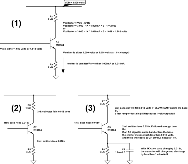
Examine this schematic, where gain is set by 3 effects.

In (1), gain is set --- almost exactly --- by ratio of Rc/Re.

In (2), we summarize the changes in Vbase, Vemitter and Vcollector, showing gain is 1.000.

In (3), we install a huge capacitor, so the change of Vemitter becomes nearly zero (less than 1 microvolt, or 0.000,0001001 volts) at 1KHz within the audio band. The gain increases, set by Rc/reac where 'reac' is the slope of the diode equation for Vdiode/Idiode of the emitter diode) from 1.000X to 51X.

Why does the change of Vemitter become nearly zero? A 1 farad capacitor needs 1amp for 1 second, to make Vcap change by 1 volt. If we only have 1mA for 1/1KHz time, we'll see less than 1 millionth of a volt change.

I chose 0.018 volts because e^0.018/0.026 is 2.000X larger, and my emitter current will predictably increase from 1mA to 2mA. The diode is non-linear, so the predicted gain of 50X is not achieved; I expect 39X.

Have fun.
schematic

simulate this circuit – Schematic created using CircuitLab

Examine this schematic, where gain is set by 3 effects.

In (1), gain is set --- almost exactly --- by ratio of Rc/Re.

In (2), we summarize the changes in Vbase, Vemitter and Vcollector, showing gain is 1.000.

In (3), we install a huge capacitor, so the Vemitter becomes nearly zero (less than 1 microvolt, or 0.000,0001 volts) at 1KHz within the audio band. The gain increases, set by Rc/reac where 'reac' is the slope of the diode equation for Vdiode/Idiode of the emitter diode.

I chose 0.018 volts because e^0.018/0.026 is 2.000X larger.

schematic

simulate this circuit – Schematic created using CircuitLab

Examine this schematic, where gain is set by 3 effects.

In (1), gain is set --- almost exactly --- by ratio of Rc/Re.

In (2), we summarize the changes in Vbase, Vemitter and Vcollector, showing gain is 1.000.

In (3), we install a huge capacitor, so the change of Vemitter becomes nearly zero (less than 1 microvolt, or 0.000,001 volts) at 1KHz within the audio band. The gain increases, set by Rc/reac where 'reac' is the slope of the diode equation for Vdiode/Idiode of the emitter diode) from 1.000X to 51X.

Why does the change of Vemitter become nearly zero? A 1 farad capacitor needs 1amp for 1 second, to make Vcap change by 1 volt. If we only have 1mA for 1/1KHz time, we'll see less than 1 millionth of a volt change.

I chose 0.018 volts because e^0.018/0.026 is 2.000X larger, and my emitter current will predictably increase from 1mA to 2mA. The diode is non-linear, so the predicted gain of 50X is not achieved; I expect 39X.

Have fun.

schematic

simulate this circuit – Schematic created using CircuitLab

Source Link
analogsystemsrf
  • 35k
  • 2
  • 20
  • 48

Examine this schematic, where gain is set by 3 effects.

In (1), gain is set --- almost exactly --- by ratio of Rc/Re.

In (2), we summarize the changes in Vbase, Vemitter and Vcollector, showing gain is 1.000.

In (3), we install a huge capacitor, so the Vemitter becomes nearly zero (less than 1 microvolt, or 0.000,0001 volts) at 1KHz within the audio band. The gain increases, set by Rc/reac where 'reac' is the slope of the diode equation for Vdiode/Idiode of the emitter diode.

I chose 0.018 volts because e^0.018/0.026 is 2.000X larger.

schematic

simulate this circuit – Schematic created using CircuitLab