Added 2 more plots, 4 caps 1UF, then inserted 10nH between each
Source Link
analogsystemsrf
  • 35k
  • 2
  • 20
  • 48

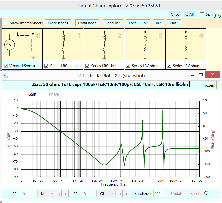
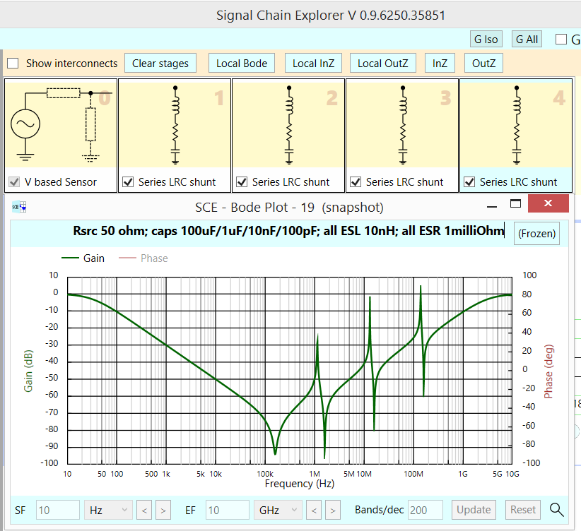
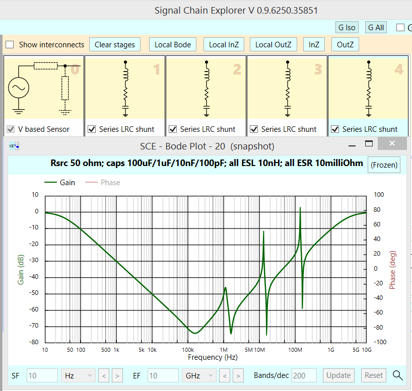
Summary: the individual capacitors need dampening; for 100uF caps, the solder and PCB foil may suffice (10milliOhm, if L = 10nH); for 1uF, use 0.1 ohm; for 10nF, use 1 ohm, etc.

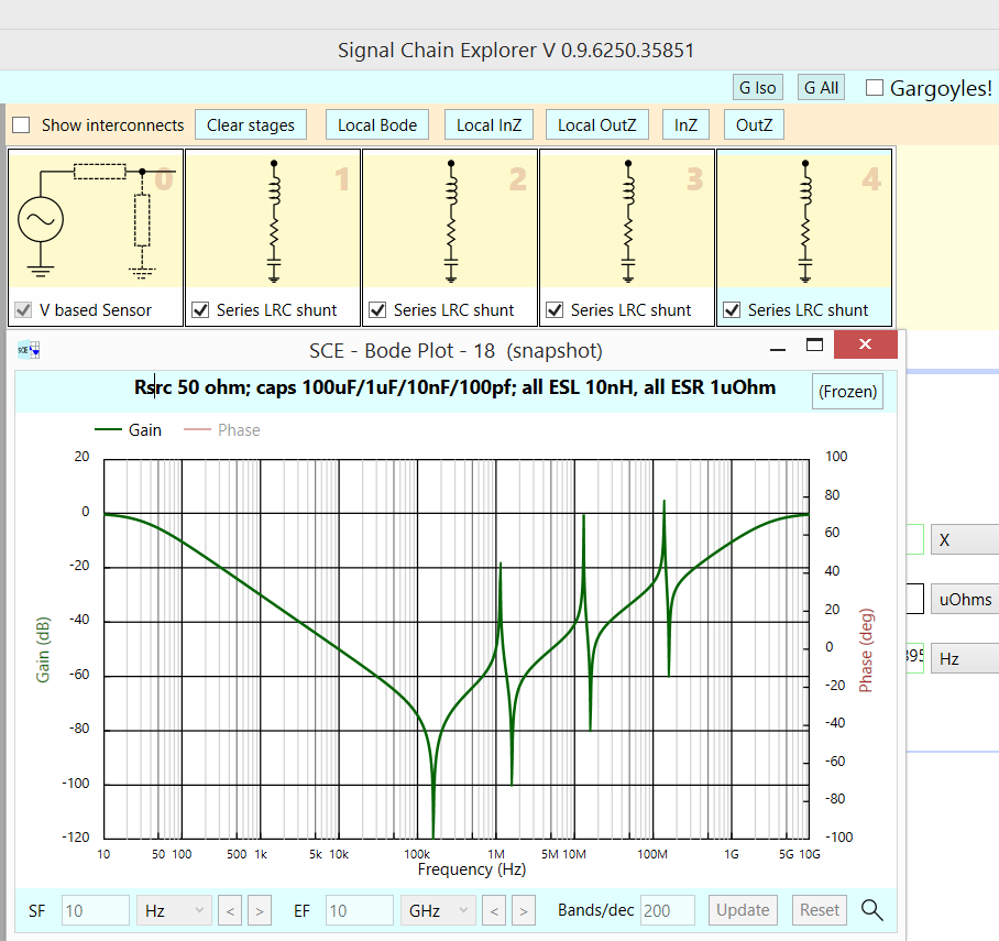
Here with 4 capacitors, 100U/1U/10n/100p and 10nH ESL, the peaking depends on the losses in each cap {I consider sqrt(L/C) a good start; thus 10nH and 10pF needs 3.1 ohms, which I have not used here; however, 10nH and 100uF need 10 milliohm, which is illustrated in the 3rd screenshot.}

Lets examine this response, with 1 microOhm ESR in each cap. Notice the lowest dip is to -120dB. Zsource is only 50 Ohms. enter image description here
Now this response, with 1 milliohm ESR in each cap. Zsource is 50 Ohms.

enter image description here

And now 10 milliohm ESR for each cap, Zsource is 50 Ohms.

enter image description here

And with 10milliOhm in each cap, with the Zsource now 1uH + 50 ohms

enter image description here

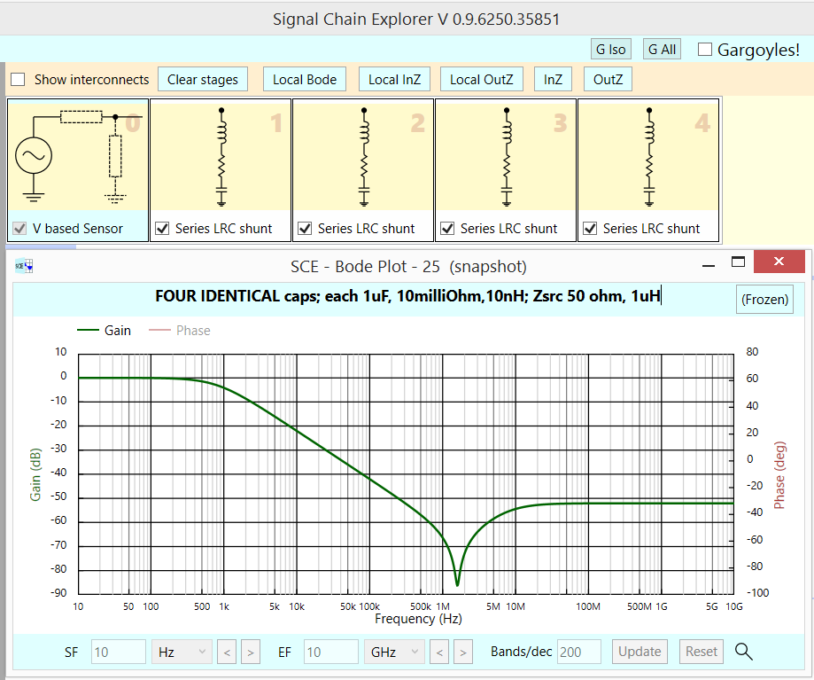
Here is (requested) SCE sim [available at robustcircuitdesign.com for free] with 4 identical 1UF caps, each with 10nH ESL and 10milliOhms. There are NO PEAKS, because the 10milliOhm dampens those peaks. [or is the Zsource, of 50 ohms and 1uH, what dampens??]

enter image description here

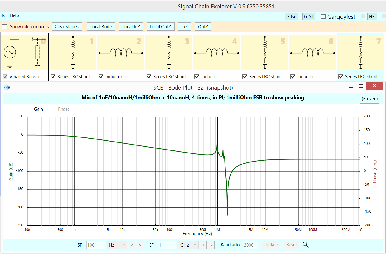
In prior sim, there was no peaking. So I insert 3 inductors between the 4 caps. Now a sim of those 4 caps + 3 inductors (PCB foil, 10nH each). Notice the peaking returns (the ESR is only 1 ONE milliohm, to show peaking), at -20dB.

enter image description here

Summary: the individual capacitors need dampening; for 100uF caps, the solder and PCB foil may suffice (10milliOhm, if L = 10nH); for 1uF, use 0.1 ohm; for 10nF, use 1 ohm, etc.

Here with 4 capacitors, 100U/1U/10n/100p and 10nH ESL, the peaking depends on the losses in each cap {I consider sqrt(L/C) a good start; thus 10nH and 10pF needs 3.1 ohms, which I have not used here; however, 10nH and 100uF need 10 milliohm, which is illustrated in the 3rd screenshot.}

Lets examine this response, with 1 microOhm ESR in each cap. Notice the lowest dip is to -120dB. Zsource is only 50 Ohms. enter image description here

Now this response, with 1 milliohm ESR in each cap. Zsource is 50 Ohms.

enter image description here

And now 10 milliohm ESR for each cap, Zsource is 50 Ohms.

enter image description here

And with 10milliOhm in each cap, with the Zsource now 1uH + 50 ohms

enter image description here

Here is (requested) SCE sim [available at robustcircuitdesign.com for free] with 4 identical 1UF caps, each with 10nH ESL and 10milliOhms. There are NO PEAKS, because the 10milliOhm dampens those peaks.

enter image description here

Summary: the individual capacitors need dampening; for 100uF caps, the solder and PCB foil may suffice (10milliOhm, if L = 10nH); for 1uF, use 0.1 ohm; for 10nF, use 1 ohm, etc.

Here with 4 capacitors, 100U/1U/10n/100p and 10nH ESL, the peaking depends on the losses in each cap {I consider sqrt(L/C) a good start; thus 10nH and 10pF needs 3.1 ohms, which I have not used here; however, 10nH and 100uF need 10 milliohm, which is illustrated in the 3rd screenshot.}

Lets examine this response, with 1 microOhm ESR in each cap. Notice the lowest dip is to -120dB. Zsource is only 50 Ohms. enter image description here

Now this response, with 1 milliohm ESR in each cap. Zsource is 50 Ohms.

enter image description here

And now 10 milliohm ESR for each cap, Zsource is 50 Ohms.

enter image description here

And with 10milliOhm in each cap, with the Zsource now 1uH + 50 ohms

enter image description here

Here is (requested) SCE sim [available at robustcircuitdesign.com for free] with 4 identical 1UF caps, each with 10nH ESL and 10milliOhms. There are NO PEAKS, because the 10milliOhm dampens those peaks. [or is the Zsource, of 50 ohms and 1uH, what dampens??]

enter image description here

In prior sim, there was no peaking. So I insert 3 inductors between the 4 caps. Now a sim of those 4 caps + 3 inductors (PCB foil, 10nH each). Notice the peaking returns (the ESR is only 1 ONE milliohm, to show peaking), at -20dB.
enter image description here

added 293 characters in body
Source Link
analogsystemsrf
  • 35k
  • 2
  • 20
  • 48

Summary: the individual capacitors need dampening; for 100uF caps, the solder and PCB foil may suffice (10milliOhm, if L = 10nH); for 1uF, use 0.1 ohm; for 10nF, use 1 ohm, etc.

Here with 4 capacitors, 100U/1U/10n/100p and 10nH ESL, the peaking depends on the losses in each cap {I consider sqrt(L/C) a good start; thus 10nH and 10pF needs 3.1 ohms, which I have not used here; however, 10nH and 100uF need 10 milliohm, which is illustrated in the 3rd screenshot.}

Lets examine this response, with 1 microOhm ESR in each cap. Notice the lowest dip is to -120dB. Zsource is only 50 Ohms. enter image description here

Now this response, with 1 milliohm ESR in each cap. Zsource is 50 Ohms.

enter image description here

And now 10 milliohm ESR for each cap, Zsource is 50 Ohms.

enter image description here

And with 10milliOhm in each cap, with the Zsource now 1uH + 50 ohms

enter image description here

Here is (requested) SCE sim [available at robustcircuitdesign.com for free] with 4 identical 1UF caps, each with 10nH ESL and 10milliOhms. There are NO PEAKS, because the 10milliOhm dampens those peaks.

enter image description here

Summary: the individual capacitors need dampening; for 100uF caps, the solder and PCB foil may suffice (10milliOhm, if L = 10nH); for 1uF, use 0.1 ohm; for 10nF, use 1 ohm, etc.

Here with 4 capacitors, 100U/1U/10n/100p and 10nH ESL, the peaking depends on the losses in each cap {I consider sqrt(L/C) a good start; thus 10nH and 10pF needs 3.1 ohms, which I have not used here; however, 10nH and 100uF need 10 milliohm, which is illustrated in the 3rd screenshot.}

Lets examine this response, with 1 microOhm ESR in each cap. Notice the lowest dip is to -120dB. Zsource is only 50 Ohms. enter image description here

Now this response, with 1 milliohm ESR in each cap. Zsource is 50 Ohms.

enter image description here

And now 10 milliohm ESR for each cap, Zsource is 50 Ohms.

enter image description here

And with 10milliOhm in each cap, with the Zsource now 1uH + 50 ohms

enter image description here

Here is (requested) SCE sim [available at robustcircuitdesign.com for free] with 4 identical 1UF caps, each with 10nH ESL and 10milliOhms. There are NO PEAKS, because the 10milliOhm dampens those peaks.

enter image description here

added 224 characters in body
Source Link
analogsystemsrf
  • 35k
  • 2
  • 20
  • 48

Summary: the individual capacitors need dampening; for 100uF caps, the solder and PCB foil may suffice (10milliOhm, if L = 10nH); for 1uF, use 0.1 ohm; for 10nF, use 1 ohm, etc.

Here with 4 capacitors, 100U/1U/10n/100p and 10nH ESL, the peaking depends on the losses in each cap {I consider sqrt(L/C) a good start; thus 10nH and 10pF needs 3.1 ohms, which I have not used here; however, 10nH and 100uF need 10 milliohm, which is illustrated in the 3rd screenshot.}

Lets examine this response, with 1 microOhm ESR in each cap. Notice the lowest dip is to -120dB. Zsource is only 50 Ohms. enter image description here

Now this response, with 1 milliohm ESR in each cap. Zsource is 50 Ohms.

enter image description here

And now 10 milliohm ESR for each cap, Zsource is 50 Ohms.

enter image description here

And with 10milliOhm in each cap, with the Zsource now 1uH + 50 ohms

enter image description here

Summary: the individual capacitors need dampening; for 100uF caps, the solder and PCB foil may suffice (10milliOhm, if L = 10nH); for 1uF, use 0.1 ohm; for 10nF, use 1 ohm, etc.

Here with 4 capacitors, 100U/1U/10n/100p and 10nH ESL, the peaking depends on the losses in each cap {I consider sqrt(L/C) a good start; thus 10nH and 10pF needs 3.1 ohms, which I have not used here; however, 10nH and 100uF need 10 milliohm, which is illustrated in the 3rd screenshot.}

Lets examine this response, with 1 microOhm ESR in each cap. Notice the lowest dip is to -120dB. Zsource is only 50 Ohms. enter image description here

Now this response, with 1 milliohm ESR in each cap. Zsource is 50 Ohms.

enter image description here

And now 10 milliohm ESR for each cap, Zsource is 50 Ohms.

enter image description here

And with 10milliOhm in each cap, with the Zsource now 1uH + 50 ohms

enter image description here

added 224 characters in body
Source Link
analogsystemsrf
  • 35k
  • 2
  • 20
  • 48
Loading
added 181 characters in body
Source Link
analogsystemsrf
  • 35k
  • 2
  • 20
  • 48
Loading
Source Link
analogsystemsrf
  • 35k
  • 2
  • 20
  • 48
Loading