corrected typos
Source Link
next-hack
  • 5.4k
  • 16
  • 34

Your circuit has several flaws.

  1. That's not an NPN transistor. It is an n-channel MOSFET.
  2. There is no motor. In that circuit you're just "shorting" (in case of an ideal MOSFET) the 9-V supply.
  3. There is no flyback diode. Unless you're using very fancy motors (e.g. piezoelectric), I assume you're using a electromagnetic motor. Therefore it will exhibit inductive behavior. Once you turn off your MOSFET/NPN transistor, the motor's inductance will try to keep the value of the current that was flowing into it (Faraday-Neuman-Lenz law). To do this, it will create "whatsoever" voltage it requires to force such current. Eventually this will reach the MOSFET/NPN breakdown voltage, which is not good.
  4. There is no pull-down resistor on the Arduino Pin. When the Arduino is in the reset state, all its I/O pins are configured as input without pull-up (the problem is even worse if the pull-up were enabled). This means that the base/gate is floating and ready to pick up all the noise. This is very dangerous as at best the motor could simply turn on (or even better, nothing occurs), at worst, the BJT/MOSFET will blow out, because you're bringing it in the "amplification" region (linear region for BJT, saturation region for MOSFET). In such region, high currents and voltages are simultaneously present, so the power dissipation is huge (you don't want this on a switch!).

I suggest you not to use a BJT, especially for relatively high-current motors. In fact, you'd need a power BJT, but power BJTs have a very poor current gain, therefore the base current should be quite high. The arduino GPIO pin might not provide enough current to fully turn on your BJT. Using a darlington transistor would not help too much, as its saturation voltage is quite high: you would need a very big heatsink.

Use instead a n-channel, LOGIC-LEVEL (i.e. low threshold voltage), low Rds(ON), power MOSFET. Which one depends of course on your requirement! Digikey or Mouser have good search engines.

The final schematics should be:
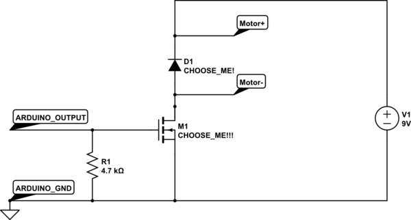
schematic

simulate this circuit – Schematic created using CircuitLab

You must choose the MOSFET and also the diode, based on the motor current specifications (yes also on the voltage, which is pretty low in your case).

The 4.7k Ohm resistor ensures that the Arduino I/O stays low (not to turn-on the MOSFET) even if you accidentally configure the pin as an input with pull-up.

If the motor is a very low power one, then you can use a BJT, instead of the MOSFET, provided that you put a suitable series resistor between R1 and the base of the BJT!!!

EDIT: If the 9V battery you're referring to is a standard PP-3 battery, then I assume your motor has a very low current. In fact, such batteries have a very limited output current capability. In that case a BJT like BC337-40 might work for you. The diode and the two resistors (one is R1, an the other - not shown for the MOSFET, but it's in series to the base of the BJT) are still required.

Your circuit has several flaws.

  1. That's not an NPN transistor. It is an n-channel MOSFET.
  2. There is no motor. In that circuit you're just "shorting" (in case of an ideal MOSFET) the 9-V supply.
  3. There is no flyback diode. Unless you're using very fancy motors (e.g. piezoelectric), I assume you're using a electromagnetic motor. Therefore it will exhibit inductive behavior. Once you turn off your MOSFET/NPN transistor, the motor's inductance will try to keep the value of the current that was flowing into it (Faraday-Neuman-Lenz law). To do this, it will create "whatsoever" voltage it requires to force such current. Eventually this will reach the MOSFET/NPN breakdown voltage, which is not good.
  4. There is no pull-down resistor on the Arduino Pin. When the Arduino is in the reset state, all its I/O pins are configured as input without pull-up (the problem is even worse if the pull-up were enabled). This means that the base/gate is floating and ready to pick up all the noise. This is very dangerous as at best the motor could simply turn on (or even better, nothing occurs), at worst, the BJT/MOSFET will blow out, because you're bringing it in the "amplification" region (linear region for BJT, saturation region for MOSFET). In such region, high currents and voltages are simultaneously present, so the power dissipation is huge (you don't want this on a switch!).

I suggest you not to use a BJT, especially for relatively high-current motors. In fact, you'd need a power BJT, but power BJTs have a very poor current gain, therefore the base current should be quite high. The arduino GPIO pin might not provide enough current to fully turn on your BJT. Using a darlington transistor would not help too much, as its saturation voltage is quite high: you would need a very big heatsink.

Use instead a n-channel, LOGIC-LEVEL (i.e. low threshold voltage), low Rds(ON), power MOSFET. Which one depends of course on your requirement! Digikey or Mouser have good search engines.

The final schematics should be:

schematic

simulate this circuit – Schematic created using CircuitLab

You must choose the MOSFET and also the diode, based on the motor current specifications (yes also on the voltage, which is pretty low in your case).

The 4.7k Ohm resistor ensures that the Arduino I/O stays low (not to turn-on the MOSFET) even if you accidentally configure the pin as an input with pull-up.

If the motor is a very low power one, then you can use a BJT, instead of the MOSFET, provided that you put a suitable series resistor between R1 and the base of the BJT!!!

EDIT: If the 9V battery you're referring to is a standard PP-3 battery, then I assume your motor has a very low current. In fact, such batteries have a very limited output current capability. In that case a BJT like BC337-40 might work for you. The diode and the two resistors (one is R1, an the other - not shown for the MOSFET, but it's in series to the base of the BJT) are still required.

Source Link
next-hack
  • 5.4k
  • 16
  • 34

Your circuit has several flaws.

  1. That's not an NPN transistor. It is an n-channel MOSFET.
  2. There is no motor. In that circuit you're just "shorting" (in case of an ideal MOSFET) the 9-V supply.
  3. There is no flyback diode. Unless you're using very fancy motors (e.g. piezoelectric), I assume you're using a electromagnetic motor. Therefore it will exhibit inductive behavior. Once you turn off your MOSFET/NPN transistor, the motor's inductance will try to keep the value of the current that was flowing into it (Faraday-Neuman-Lenz law). To do this, it will create "whatsoever" voltage it requires to force such current. Eventually this will reach the MOSFET/NPN breakdown voltage, which is not good.
  4. There is no pull-down resistor on the Arduino Pin. When the Arduino is in the reset state, all its I/O pins are configured as input without pull-up (the problem is even worse if the pull-up were enabled). This means that the base/gate is floating and ready to pick up all the noise. This is very dangerous as at best the motor could simply turn on (or even better, nothing occurs), at worst, the BJT/MOSFET will blow out, because you're bringing it in the "amplification" region (linear region for BJT, saturation region for MOSFET). In such region, high currents and voltages are simultaneously present, so the power dissipation is huge (you don't want this on a switch!).

I suggest you not to use a BJT, especially for relatively high-current motors. In fact, you'd need a power BJT, but power BJTs have a very poor current gain, therefore the base current should be quite high. The arduino GPIO pin might not provide enough current to fully turn on your BJT. Using a darlington transistor would not help too much, as its saturation voltage is quite high: you would need a very big heatsink.

Use instead a n-channel, LOGIC-LEVEL (i.e. low threshold voltage), low Rds(ON), power MOSFET. Which one depends of course on your requirement! Digikey or Mouser have good search engines.

The final schematics should be:

schematic

simulate this circuit – Schematic created using CircuitLab

You must choose the MOSFET and also the diode, based on the motor current specifications (yes also on the voltage, which is pretty low in your case).

The 4.7k Ohm resistor ensures that the Arduino I/O stays low (not to turn-on the MOSFET) even if you accidentally configure the pin as an input with pull-up.

If the motor is a very low power one, then you can use a BJT, instead of the MOSFET, provided that you put a suitable series resistor between R1 and the base of the BJT!!!