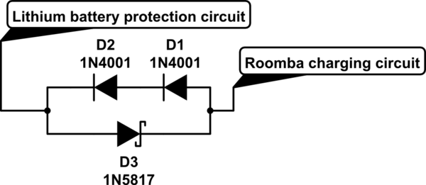
Two silicon diodes in series should be able to drop the required 1.2V (or a little bit more) from 18V to ~16.8V when charging.
When discharging, a Schottky diode in antiparallel will let the current flow back out of the Lithium battery circuit with only a small voltage drop.
Something like this:

simulate this circuit – Schematic created using CircuitLab
This assumes that the same wire is used for charging and discharging, and that the circuits behave as you have described.
In the real world you may or may not need to tweak some additional things to make it work, but in principle this should do it.
Take care to use diodes that can take the necessary current and dissipate the power.
The Schottky diode should have as low a voltage drop as possible. The reverse breakdown voltage of the Schottky doesn't need to be very high though, since the regular diodes are limiting that voltage.
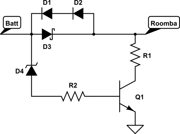
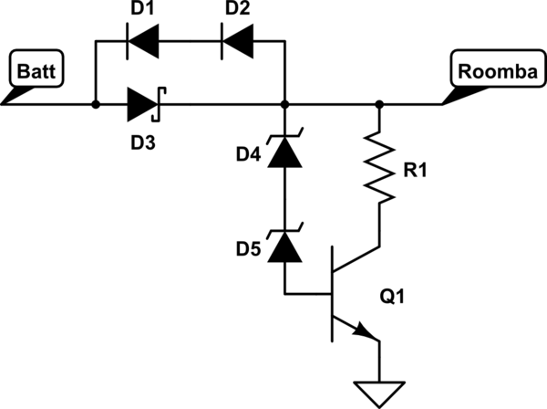
If the Roomba charger is looking for a dip in voltage that indicates that the battery is full, the circuit will have to be more complex. Perhaps a shunt resistor and a transistor triggered by one or more zener diodes would work, something like this:

You would have to choose the right Zener voltage(s) to trigger the transistor right before the Lithium battery protection circuit reaches its cutoff voltage. R2 should limit the base current of the transistor, while R1 pulls the voltage at the Roomba charger output down. R1 needs to be able to:
- Pull down the voltage at the Roomba charger output by ~5 mV per cell in the NiMH pack, to simulate a full NiMH battery.
- Handle the full 18V for however long it takes for the charger to realize that the battery is full and stop charging.
And the transistor needs to be able to withstand the same current.
A circuit like this should be tested thoroughly before put into use, though. If the charger doesn't trigger and shut off correctly every time, you might risk R1 getting hot enough to set something on fire, that's of course depending on how much power it will have to dissipate. You can run the numbers and even simulate some circuits, but also don't forget to run enough real-life tests.
BTW, if the Lithium-ion protection board has a LED (or some output pin) that turns on (high) when it reaches max voltage and cuts off, you might be able to use that output to trigger the transistor instead of using a zener diode.

