added 9 characters in body
Source Link
jluu
  • 343
  • 3
  • 5

Here is what worked for me:

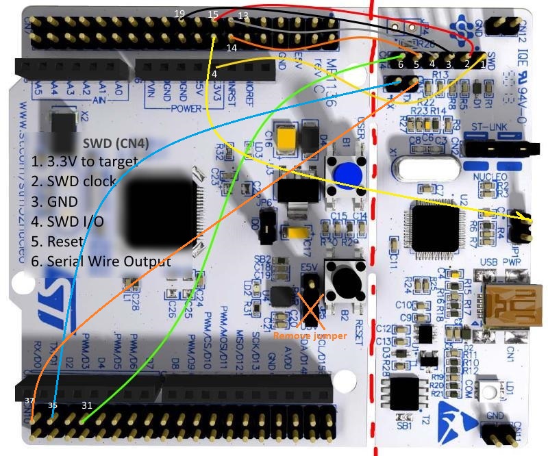
If the stlink is actually broken off, the nucleo should be powered by the stlink, the yellow wire going from the the upper pin of jp1JP1 on the stlink to pin 16 the ofof the nucleo supplies the 3.3V (the other yellow wire going from nucleo pin 4 to swd/cn4 pin 1 is used by the stlink to measure the voltage).

As with measuring the voltage: also make sure that R9 on the stlink exists, on mine it was empty, I had to solder a 4K7 resistor, before that, the voltage was read as 0V by the stlink and open OCD was issuing a warning message "target voltage may be too low for reliable debugging”

The jumper on the nucleo JP5 should be removed as to deconnect from the output of the onboard regulator.

If you are programming another nucleo where the stlink is NOT broken off, on the other nucleo stlink the 0 ohm resistor on SB12 should be removed as to deconnect the reset line going from the NOT broken off stlink to the nucleo, otherwise the connected stlink, when not powered will hold the reset line.

Optional connections (35, 37) to RX and TX require connecting the bridges SB62 and SB63 under the nucleo board, this allows to use the virtual comm port of the stlink wire connections schematic
Here is what worked for me:

If the stlink is actually broken off, the nucleo should be powered by the stlink, the yellow wire going from the the upper pin of jp1 on the stlink to pin 16 the of the nucleo supplies the 3.3V (the other yellow wire going from nucleo pin 4 to swd/cn4 pin 1 is used by the stlink to measure the voltage).

As with measuring the voltage: also make sure that R9 on the stlink exists, on mine it was empty, I had to solder a 4K7 resistor, before that voltage was read as 0V by the stlink and open OCD was issuing a warning message "target voltage may be too low for reliable debugging”

The jumper on the nucleo JP5 should be removed as to deconnect from the output of the onboard regulator.

If you are programming another nucleo where the stlink is NOT broken off, on the other nucleo stlink the 0 ohm resistor on SB12 should be removed as to deconnect the reset line going from the NOT broken off stlink to the nucleo, otherwise the connected stlink, when not powered will hold the reset line.

Optional connections to RX and TX require connecting the bridges SB62 and SB63 under the nucleo board, this allows to use the virtual comm port of the stlink wire connections schematic

Here is what worked for me:

If the stlink is actually broken off, the nucleo should be powered by the stlink, the yellow wire going from the the upper pin of JP1 on the stlink to pin 16 of the nucleo supplies the 3.3V (the other yellow wire going from nucleo pin 4 to swd/cn4 pin 1 is used by the stlink to measure the voltage).

As with measuring the voltage: also make sure that R9 on the stlink exists, on mine it was empty, I had to solder a 4K7 resistor, before that, the voltage was read as 0V by the stlink and open OCD was issuing a warning message "target voltage may be too low for reliable debugging”

The jumper on the nucleo JP5 should be removed as to deconnect from the output of the onboard regulator.

If you are programming another nucleo where the stlink is NOT broken off, on the other nucleo stlink the 0 ohm resistor on SB12 should be removed as to deconnect the reset line going from the NOT broken off stlink to the nucleo, otherwise the connected stlink, when not powered will hold the reset line.

Optional connections (35, 37) to RX and TX require connecting the bridges SB62 and SB63 under the nucleo board, this allows to use the virtual comm port of the stlink wire connections schematic
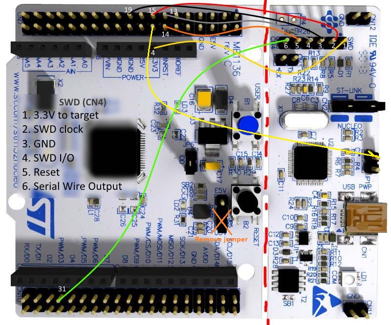
add serial connections
Source Link
jluu
  • 343
  • 3
  • 5

Here is what worked for me:

If the stlink is actually broken off, the nucleo should be powered by the stlink, the yellow wire going from the the upper pin of jp1 on the stlink to pin 16 the of the nucleo supplies the 3.3V (the other yellow wire going from nucleo pin 4 to swd/cn4 pin 1 is used by the stlink to measure the voltage).

As with measuring the voltage: also make sure that R9 on the stlink exists, on mine it was empty, I had to solder a 4K7 resistor, before that voltage was read as 0V by the stlink and open OCD was issuing a warning message "target voltage may be too low for reliable debugging”

The jumper on the nucleo JP5 should be removed as to deconnect from the output of the onboard regulator.

If you are programming another nucleo where the stlink is NOT broken off, on the other nucleo stlink the 0 ohm resistor on SB12 should be removed as to deconnect the reset line going from the NOT broken off stlink to the nucleo, otherwise the connected stlink, when not powered will hold the reset line.

wiring drawn on a photo of nucleo board Optional connections to RX and TX require connecting the bridges SB62 and SB63 under the nucleo board, this allows to use the virtual comm port of the stlink wire connections schematic

Here is what worked for me:

If the stlink is actually broken off, the nucleo should be powered by the stlink, the yellow wire going from the the upper pin of jp1 on the stlink to pin 16 the of the nucleo supplies the 3.3V (the other yellow wire going from nucleo pin 4 to swd/cn4 pin 1 is used by the stlink to measure the voltage).

As with measuring the voltage: also make sure that R9 on the stlink exists, on mine it was empty, I had to solder a 4K7 resistor, before that voltage was read as 0V by the stlink and open OCD was issuing a warning message "target voltage may be too low for reliable debugging”

The jumper on the nucleo JP5 should be removed as to deconnect from the output of the onboard regulator.

If you are programming another nucleo where the stlink is NOT broken off, on the other nucleo stlink the 0 ohm resistor on SB12 should be removed as to deconnect the reset line going from the NOT broken off stlink to the nucleo, otherwise the connected stlink, when not powered will hold the reset line.

wiring drawn on a photo of nucleo board

Here is what worked for me:

If the stlink is actually broken off, the nucleo should be powered by the stlink, the yellow wire going from the the upper pin of jp1 on the stlink to pin 16 the of the nucleo supplies the 3.3V (the other yellow wire going from nucleo pin 4 to swd/cn4 pin 1 is used by the stlink to measure the voltage).

As with measuring the voltage: also make sure that R9 on the stlink exists, on mine it was empty, I had to solder a 4K7 resistor, before that voltage was read as 0V by the stlink and open OCD was issuing a warning message "target voltage may be too low for reliable debugging”

The jumper on the nucleo JP5 should be removed as to deconnect from the output of the onboard regulator.

If you are programming another nucleo where the stlink is NOT broken off, on the other nucleo stlink the 0 ohm resistor on SB12 should be removed as to deconnect the reset line going from the NOT broken off stlink to the nucleo, otherwise the connected stlink, when not powered will hold the reset line.

Optional connections to RX and TX require connecting the bridges SB62 and SB63 under the nucleo board, this allows to use the virtual comm port of the stlink wire connections schematic

improved explanation
Source Link
jluu
  • 343
  • 3
  • 5

Here is what worked for me:

If the stlink is actually broken off, the nucleo should be powered by the stlink, the yellow wire going from the the upper pin of jp1 on the stlink to pin 16 the of the nucleo supplies the 3.3V (the other yellow wire going from nucleo pin 4 to swd/cn4 pin 1 is used by the stlink to measure the voltage).

As with measuring the voltage: also make sure that R9 on the stlink exists, on mine it was empty, I had to solder a 4K7 resistor, before that voltage was read as 0V by the stlink and open OCD was issuing a warning message "target voltage may be too low for reliable debugging”

The jumper on the nucleo JP5 should be removed as to deconnect from the output of the onboard regulator.

If you are programming another nucleo's stlinknucleo where the stlink is NOT broken off, on thisthe other nucleo stlink the 0 ohm resistor on SB12 should be removed as to deconnect the reset line going from the NOT broken off stlink to the nucleo, otherwise the connected stlink, when not powered will hold the reset line.

wiring drawn on a photo of nucleo board

Here is what worked for me:

If the stlink is actually broken off, the nucleo should be powered by the stlink, the yellow wire going from the the upper pin of jp1 on the stlink to pin 16 the of the nucleo supplies the 3.3V (the other yellow wire going from nucleo pin 4 to swd/cn4 pin 1 is used by the stlink to measure the voltage).

As with measuring the voltage: also make sure that R9 on the stlink exists, on mine it was empty, I had to solder a 4K7 resistor, before that voltage was read as 0V by the stlink and open OCD was issuing a warning message "target voltage may be too low for reliable debugging”

The jumper on the nucleo JP5 should be removed as to deconnect from the output of the onboard regulator.

If you are programming another nucleo's stlink where the stlink is NOT broken off, on this stlink the 0 ohm resistor on SB12 should be removed as to deconnect the reset line going from the NOT broken off stlink to the nucleo, otherwise the connected stlink, when not powered will hold the reset line.

wiring drawn on a photo of nucleo board

Here is what worked for me:

If the stlink is actually broken off, the nucleo should be powered by the stlink, the yellow wire going from the the upper pin of jp1 on the stlink to pin 16 the of the nucleo supplies the 3.3V (the other yellow wire going from nucleo pin 4 to swd/cn4 pin 1 is used by the stlink to measure the voltage).

As with measuring the voltage: also make sure that R9 on the stlink exists, on mine it was empty, I had to solder a 4K7 resistor, before that voltage was read as 0V by the stlink and open OCD was issuing a warning message "target voltage may be too low for reliable debugging”

The jumper on the nucleo JP5 should be removed as to deconnect from the output of the onboard regulator.

If you are programming another nucleo where the stlink is NOT broken off, on the other nucleo stlink the 0 ohm resistor on SB12 should be removed as to deconnect the reset line going from the NOT broken off stlink to the nucleo, otherwise the connected stlink, when not powered will hold the reset line.

wiring drawn on a photo of nucleo board

added 11 characters in body
Source Link
jluu
  • 343
  • 3
  • 5
Loading
precisions
Source Link
jluu
  • 343
  • 3
  • 5
Loading
mention fix R9
Source Link
jluu
  • 343
  • 3
  • 5
Loading
Source Link
jluu
  • 343
  • 3
  • 5
Loading