I've got a doozy of an Altium question:
I've got a chip antenna (2mm x 2mm or something like that).
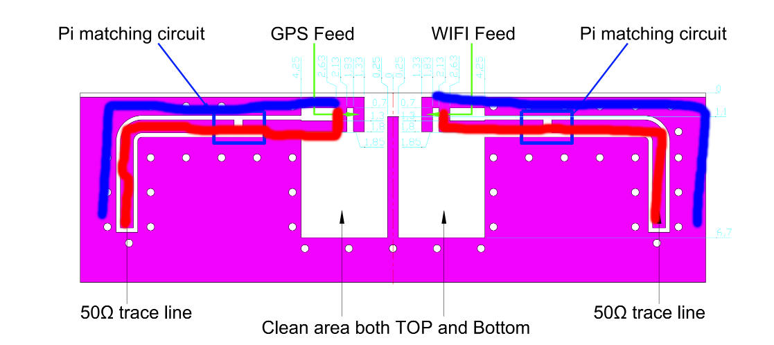
The datasheet of the chip antenna calls for a 50 ohm line (in red in the graphic)
It also calls for a GND line (in blue) that intersects the 50 ohm trace.
Supposing I draw this layout in Solidworks and import it as a top layer fill, so the geometry of the traces are correct?
How would you assign the nets and/or layout the pads to the top layer fill of this shape?
I've tried creating the separate fill and it seems you can't assign just a chunk of the top layer fill to a net.
In this post showing a kind of similiar issue, what did the user do here to create those pad points? Did he just create a top layer pad and drop it on the fill?
This is like a pro-grade Altium problem.
