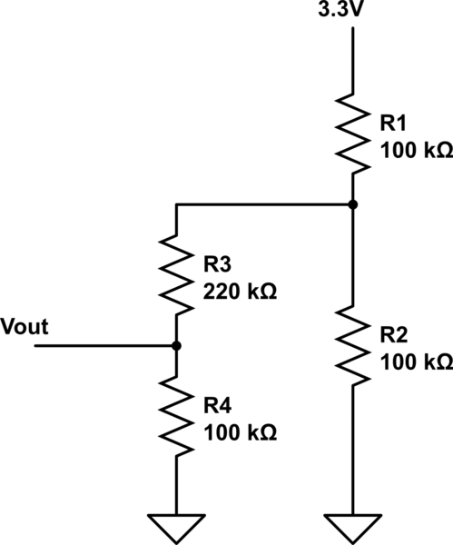
As a followup to my previous question it turns out there was more to it than I thought. It seems that between my voltage divider and the ADC on the ESP there is a second voltage divider to step down the maximum of 3.3V from the development board to a maximum of 1V at the ESP unit.
So it actually looks like this:

simulate this circuit – Schematic created using CircuitLab
I'm told R2 in parallel with the the R3/R4 (100K/220K) divider makes the R1/R2 divider act like it was 100K and 76K at Vout such that 3.3V at the first divider yields 1.42V at Vout. That is consistent with what I measure with a DMM.
Can the two voltage dividers as diagrammed above be expressed mathematically? IOW, mathematically, if one voltage divider is Vout=Vin*(R2/(R1+R2)) is there an equation for two voltage dividers such as the one above?
Update:
So I've been struggling with the math and I have come the conclusion that my 50 year-old brain is definitely not what my teenage brain was when it comes to algebra. It's not something I've needed since learning it in high school and it's gotten really dusty. :-( Let me apologise profusely for my rusty alegbra in advance. But...
If R3 and R4 are fixed at 220kΩ and 100kΩ respectively and R2 will be a fixed value also (I'm not sure what yet, but it will be a value that will give me good readings on R1 for the range of values on R1 that I am interested in) and R1 will be a sensor with variable resistance (i.e. a thermistor), what is the equation to figure out the resistance of R1 given a value for R2 and a value for Vout?
For argument's sake, let's say R2 is 5.1kΩ since that's a value that has been giving me good readings in the range of temperatures on R1 that I am interested in at the moment. But I'd like to be able to change in my equation in the future if my range of interest in R1 changes.
