added 19 characters in body
Source Link
Ale..chenski
  • 42.4k
  • 3
  • 44
  • 113

Some of this heat propagates upwards, but some must also go downwards towards the PCB. I don't know the ratio.

That's true, heat propagates in all directions. Unfortunately, the rate of propagation (also known to be characterized as thermal resistance) is very different.

A CPU must be connected with peripherals/memory somehow, so it has 1000 - 2000 pins for that purpose. So the electrical path (fanout) must be provided, which is done via printed circuit board technology. Unfortunately, even if impregnated with bunch of copper wires/layers, the whole PCB thing doesn't conduct heat very well. But this is unavoidable - you need connections.

Early CPUs (i386-i486) were cooled mostly via PCB path, in early 90-th the PC CPUs had no heat sink on top. Many chips with traditional wire-bond mounting (silicon chip on the bottom, pads connected with wires from top pads to lead frame) may have thermal slug on the bottom, because this is the path of least thermal resistance.

Then the flip-chip packaging technology was invented, so the die is on the top of package, upside-down, and all electrical connection is done via electrically conductive bumps on the bottom. So the path of least resistance is now going through the top of processors. That's where all extra tricks are used, to spread the heat from relatively small die (1 sq.sm) to bigger heat sink, etc.

Fortunately, CPU design teams include sizable engineering departments who conduct thermal modeling of the CPU die and entire packaging. The initial data came from digital design, and then expensive 3-D solvers give overall picture of heat distribution and fluxes. The modeling obviously includes thermal models of CPU sockets/pins and mainboards. I would suggest to trust them with solutions they provide, they know their business. Apparently some extra cooling from the bottom of PCB just isn't worth extra effort.

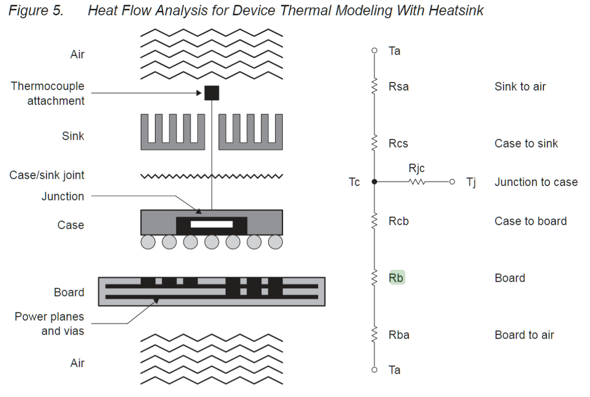
ADDITION: Here is a lump model of a FBGA chip, which can give an idea to, say, LGA2011 Intel thermal model.

enter image description here

While the multi-layer PCB with thermal vias and 25% copper content might have somewhat good thermal performance, modern/practical LGA2011 system has one important element, a socket. The socket has a needle-type spring contacts under each pad. It is quite obvious that the total bulk of metal contact across the socket is quite smaller than the bulk copper slug on the top of CPU. I would say it is no more than 1/100 of the slug area, likely much less. Therefore it must be obvious that the thermal resistance of LGA2011 socket is at least 1/100100X of the top direction, or no more than 1% of heat can go down. I guess for this reason Intel thermal guides totally ignore the bottom thermal path, it is not mentioned.

Some of this heat propagates upwards, but some must also go downwards towards the PCB. I don't know the ratio.

That's true, heat propagates in all directions. Unfortunately, the rate of propagation (also known to be characterized as thermal resistance) is very different.

A CPU must be connected with peripherals/memory somehow, so it has 1000 - 2000 pins for that purpose. So the electrical path (fanout) must be provided, which is done via printed circuit board technology. Unfortunately, even if impregnated with bunch of copper wires/layers, the whole PCB thing doesn't conduct heat very well. But this is unavoidable - you need connections.

Early CPUs (i386-i486) were cooled mostly via PCB path, in early 90-th the PC CPUs had no heat sink on top. Many chips with traditional wire-bond mounting (silicon chip on the bottom, pads connected with wires from top pads to lead frame) may have thermal slug on the bottom, because this is the path of least thermal resistance.

Then the flip-chip packaging technology was invented, so the die is on the top of package, upside-down, and all electrical connection is done via electrically conductive bumps on the bottom. So the path of least resistance is now going through the top of processors. That's where all extra tricks are used, to spread the heat from relatively small die (1 sq.sm) to bigger heat sink, etc.

Fortunately, CPU design teams include sizable engineering departments who conduct thermal modeling of the CPU die and entire packaging. The initial data came from digital design, and then expensive 3-D solvers give overall picture of heat distribution and fluxes. The modeling obviously includes thermal models of CPU sockets/pins and mainboards. I would suggest to trust them with solutions they provide, they know their business. Apparently some extra cooling from the bottom of PCB just isn't worth extra effort.

ADDITION: Here is a lump model of a FBGA chip, which can give an idea to, say, LGA2011 Intel thermal model.

enter image description here

While the multi-layer PCB with thermal vias and 25% copper content might have somewhat good thermal performance, modern/practical LGA2011 system has one important element, a socket. The socket has a needle-type spring contacts under each pad. It is quite obvious that the total bulk of metal contact across the socket is quite smaller than the bulk copper slug on the top of CPU. I would say it is no more than 1/100 of the slug area, likely much less. Therefore it must be obvious that the thermal resistance of LGA2011 socket is at least 1/100 of the top direction, or no more than 1%. I guess for this reason Intel thermal guides totally ignore the bottom thermal path, it is not mentioned.

Some of this heat propagates upwards, but some must also go downwards towards the PCB. I don't know the ratio.

That's true, heat propagates in all directions. Unfortunately, the rate of propagation (also known to be characterized as thermal resistance) is very different.

A CPU must be connected with peripherals/memory somehow, so it has 1000 - 2000 pins for that purpose. So the electrical path (fanout) must be provided, which is done via printed circuit board technology. Unfortunately, even if impregnated with bunch of copper wires/layers, the whole PCB thing doesn't conduct heat very well. But this is unavoidable - you need connections.

Early CPUs (i386-i486) were cooled mostly via PCB path, in early 90-th the PC CPUs had no heat sink on top. Many chips with traditional wire-bond mounting (silicon chip on the bottom, pads connected with wires from top pads to lead frame) may have thermal slug on the bottom, because this is the path of least thermal resistance.

Then the flip-chip packaging technology was invented, so the die is on the top of package, upside-down, and all electrical connection is done via electrically conductive bumps on the bottom. So the path of least resistance is now going through the top of processors. That's where all extra tricks are used, to spread the heat from relatively small die (1 sq.sm) to bigger heat sink, etc.

Fortunately, CPU design teams include sizable engineering departments who conduct thermal modeling of the CPU die and entire packaging. The initial data came from digital design, and then expensive 3-D solvers give overall picture of heat distribution and fluxes. The modeling obviously includes thermal models of CPU sockets/pins and mainboards. I would suggest to trust them with solutions they provide, they know their business. Apparently some extra cooling from the bottom of PCB just isn't worth extra effort.

ADDITION: Here is a lump model of a FBGA chip, which can give an idea to, say, LGA2011 Intel thermal model.

enter image description here

While the multi-layer PCB with thermal vias and 25% copper content might have somewhat good thermal performance, modern/practical LGA2011 system has one important element, a socket. The socket has a needle-type spring contacts under each pad. It is quite obvious that the total bulk of metal contact across the socket is quite smaller than the bulk copper slug on the top of CPU. I would say it is no more than 1/100 of the slug area, likely much less. Therefore it must be obvious that the thermal resistance of LGA2011 socket is at least 100X of the top direction, or no more than 1% of heat can go down. I guess for this reason Intel thermal guides totally ignore the bottom thermal path, it is not mentioned.

added 1056 characters in body
Source Link
Ale..chenski
  • 42.4k
  • 3
  • 44
  • 113

Some of this heat propagates upwards, but some must also go downwards towards the PCB. I don't know the ratio.

That's true, heat propagates in all directions. Unfortunately, the rate of propagation (also known to be characterized as thermal resistance) is very different.

A CPU must be connected with peripherals/memory somehow, so it has 1000 - 2000 pins for that purpose. So the electrical path (fanout) must be provided, which is done via printed circuit board technology. Unfortunately, even if impregnated with bunch of copper wires/layers, the whole PCB thing doesn't conduct heat very well. But this is unavoidable - you need connections.

Early CPUs (i386-i486) were cooled mostly via PCB path, in early 90-th the PC CPUs had no heat sink on top. Many chips with traditional wire-bond mounting (silicon chip on the bottom, pads connected with wires from top pads to lead frame) may have thermal slug on the bottom, because this is the path of least thermal resistance.

Then the flip-chip packaging technology was invented, so the die is on the top of package, upside-down, and all electrical connection is done via electrically conductive bumps on the bottom. So the path of least resistance is now going through the top of processors. That's where all extra tricks are used, to spread the heat from relatively small die (1 sq.sm) to bigger heat sink, etc.

Fortunately, CPU design teams include sizable engineering departments who conduct thermal modeling of the CPU die and entire packaging. The initial data came from digital design, and then expensive 3-D solvers give overall picture of heat distribution and fluxes. The modeling obviously includes thermal models of CPU sockets/pins and mainboards. I would suggest to trust them with solutions they provide, they know their business. Apparently some extra cooling from the bottom of PCB just isn't worth extra effort.

ADDITION: Here is a lump model of a FBGA chip, which can give an idea to, say, LGA2011 Intel thermal model.

enter image description here

While the multi-layer PCB with thermal vias and 25% copper content might have somewhat good thermal performance, modern/practical LGA2011 system has one important element, a socket. The socket has a needle-type spring contacts under each pad. It is quite obvious that the total bulk of metal contact across the socket is quite smaller than the bulk copper slug on the top of CPU. I would say it is no more than 1/100 of the slug area, likely much less. Therefore it must be obvious that the thermal resistance of LGA2011 socket is at least 1/100 of the top direction, or no more than 1%. I guess for this reason Intel thermal guides totally ignore the bottom thermal path, it is not mentioned.

Some of this heat propagates upwards, but some must also go downwards towards the PCB. I don't know the ratio.

That's true, heat propagates in all directions. Unfortunately, the rate of propagation (also known to be characterized as thermal resistance) is very different.

A CPU must be connected with peripherals/memory somehow, so it has 1000 - 2000 pins for that purpose. So the electrical path (fanout) must be provided, which is done via printed circuit board technology. Unfortunately, even if impregnated with bunch of copper wires/layers, the whole PCB thing doesn't conduct heat very well. But this is unavoidable - you need connections.

Early CPUs (i386-i486) were cooled mostly via PCB path, in early 90-th the PC CPUs had no heat sink on top. Many chips with traditional wire-bond mounting (silicon chip on the bottom, pads connected with wires from top pads to lead frame) may have thermal slug on the bottom, because this is the path of least thermal resistance.

Then the flip-chip packaging technology was invented, so the die is on the top of package, upside-down, and all electrical connection is done via electrically conductive bumps on the bottom. So the path of least resistance is now going through the top of processors. That's where all extra tricks are used, to spread the heat from relatively small die (1 sq.sm) to bigger heat sink, etc.

Fortunately, CPU design teams include sizable engineering departments who conduct thermal modeling of the CPU die and entire packaging. The initial data came from digital design, and then expensive 3-D solvers give overall picture of heat distribution and fluxes. The modeling obviously includes thermal models of CPU sockets/pins and mainboards. I would suggest to trust them with solutions they provide, they know their business. Apparently some extra cooling from the bottom of PCB just isn't worth extra effort.

ADDITION: Here is a lump model of a FBGA chip, which can give an idea to, say, LGA2011 Intel thermal model.

enter image description here

While the multi-layer PCB with thermal vias and 25% copper content might have somewhat good thermal performance, modern/practical LGA2011 system has one important element, a socket. The socket has a needle-type spring contacts under each pad. It is quite obvious that the total bulk of metal contact across the socket is quite smaller than the bulk copper slug on the top of CPU. I would say it is no more than 1/100 of the slug area, likely much less. Therefore it must be obvious that the thermal resistance of LGA2011 socket is at least 1/100 of the top direction, or no more than 1%. I guess for this reason Intel thermal guides totally ignore the bottom thermal path, it is not mentioned.

added 83 characters in body
Source Link
Ale..chenski
  • 42.4k
  • 3
  • 44
  • 113

Some of this heat propagates upwards, but some must also go downwards towards the PCB. I don't know the ratio.

That's true, heat propagates in all directions. Unfortunately, the rate of propagation (also known to be characterized as thermal resistance) is very different.

A CPU must be connected with peripherals/memory somehow, so it has 1000 - 2000 pins for that purpose. So the electrical path (fanout) must be provided, which is done via printed circuit board technology. Unfortunately, even if impregnated with bunch of copper wires/layers, the whole PCB thing doesn't conduct heat very well. But this is unavoidable - you need connections.

Early CPUs (i386-i486) were cooled mostly via PCB path, in early 90-th the PC CPUs had no heat sink on top. Many chips with traditional wire-bond mounting (silicon chip on the bottom, pads connected with wires from top pads to lead frame) may have thermal slug on the bottom, because this is the path of least thermal resistance.

Then the flip-chip packaging technology was invented, so the die is on the top of package, upside-down, and all electrical connection is done via electrically conductive bumps on the bottom. So the path of least resistance is now going through the top of processors. That's where all extra tricks are used, to spread the heat from relatively small die (1 sq.sm) to bigger heat sink, etc.

Fortunately, CPU design teams include sizable engineering departments who conduct thermal modeling of the CPU die and entire packaging. The initial data came from digital design, and then expensive 3-D solvers give overall picture of heat distribution and fluxes. The modeling obviously includes thermal models of CPU sockets/pins and mainboards. I would suggest to trust them with solutions they provide, they know their business. Apparently some extra cooling from the bottom of PCB just isn't worth extra effort.

Some of this heat propagates upwards, but some must also go downwards towards the PCB. I don't know the ratio.

That's true, heat propagates in all directions. Unfortunately, the rate of propagation (also known to be characterized as thermal resistance) is very different.

A CPU must be connected with peripherals/memory somehow, so it has 1000 - 2000 pins for that purpose. So the electrical path (fanout) must be provided, which is done via printed circuit board technology. Unfortunately, even if impregnated with bunch of copper wires/layers, the whole PCB thing doesn't conduct heat very well. But this is unavoidable - you need connections.

Early CPUs (i386-i486) were cooled mostly via PCB path, in early 90-th the PC CPUs had no heat sink on top. Many chips with traditional wire-bond mounting (silicon chip on the bottom, pads connected with wires from top pads to lead frame) may have thermal slug on the bottom, because this is the path of least thermal resistance.

Then the flip-chip packaging technology was invented, so the die is on the top of package, upside-down, and all electrical connection is done via electrically conductive bumps on the bottom. So the path of least resistance is now going through the top of processors. That's where all extra tricks are used, to spread the heat from relatively small die (1 sq.sm) to bigger heat sink, etc.

Fortunately, CPU design teams include sizable engineering departments who conduct thermal modeling of the CPU die and entire packaging. The initial data came from digital design, and then expensive 3-D solvers give overall picture of heat distribution and fluxes. The modeling obviously includes thermal models of CPU sockets/pins and mainboards. I would suggest to trust them with solutions they provide, they know their business.

Some of this heat propagates upwards, but some must also go downwards towards the PCB. I don't know the ratio.

That's true, heat propagates in all directions. Unfortunately, the rate of propagation (also known to be characterized as thermal resistance) is very different.

A CPU must be connected with peripherals/memory somehow, so it has 1000 - 2000 pins for that purpose. So the electrical path (fanout) must be provided, which is done via printed circuit board technology. Unfortunately, even if impregnated with bunch of copper wires/layers, the whole PCB thing doesn't conduct heat very well. But this is unavoidable - you need connections.

Early CPUs (i386-i486) were cooled mostly via PCB path, in early 90-th the PC CPUs had no heat sink on top. Many chips with traditional wire-bond mounting (silicon chip on the bottom, pads connected with wires from top pads to lead frame) may have thermal slug on the bottom, because this is the path of least thermal resistance.

Then the flip-chip packaging technology was invented, so the die is on the top of package, upside-down, and all electrical connection is done via electrically conductive bumps on the bottom. So the path of least resistance is now going through the top of processors. That's where all extra tricks are used, to spread the heat from relatively small die (1 sq.sm) to bigger heat sink, etc.

Fortunately, CPU design teams include sizable engineering departments who conduct thermal modeling of the CPU die and entire packaging. The initial data came from digital design, and then expensive 3-D solvers give overall picture of heat distribution and fluxes. The modeling obviously includes thermal models of CPU sockets/pins and mainboards. I would suggest to trust them with solutions they provide, they know their business. Apparently some extra cooling from the bottom of PCB just isn't worth extra effort.

Source Link
Ale..chenski
  • 42.4k
  • 3
  • 44
  • 113
Loading