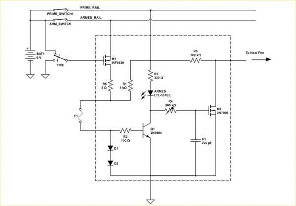
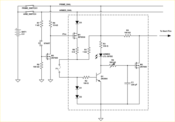
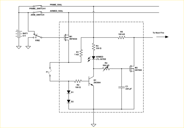
A chain of something like this might work.


simulate this circuitsimulate this circuit – Schematic created using CircuitLab
Initially low current flows through the igniter through R1 and sets up a voltage across D1 and D2 that biases Q1 on. Q1 then pulls the LED low and keeps M2 off. NOTE: I increased the battery to six volts to compensate for the diode drops.
When the gate of M1 is pulled low, it turns on and lets the full current flow through the igniter from the ARMED_RAIL. This current is expected to fuse the igniter.
When the ignoter fuses, Q1 will turn off allowing C1 to charge through the potentiometer R4. When it reaches the gate threshold voltage of M2 the latter will turn on pulling the gate of the next state low firing the next fuse.
R5 ensures the next gate is pulled high.
R6 limits the current to ~1A, and needs to be a power resistor, though it should not be on long.
Note the separate power lines. One applies power to the switches the other is a safety switch that prevents full power from ever being applied to the igniters. Use of a key-switch for that is prudent.

