First, you need to ask yourself a question know how analog PWM work.
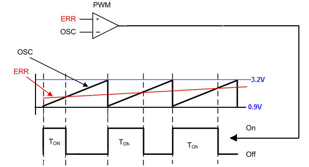
This diagram explains everything you need to know.
As you can see we have a comparator and two signals at the input.
At noninverting we apply the "error" voltage and at the inverting input, we apply sawtooth waveform from the internal/external oscillator.
And by changing the voltage at noninverting input we can change the duration of the output pulse. Notice that when the value of the input "error" signal is greater than that of the sawtooth wave, the output of the comparator is high. Otherwise, the output of the comparator is low.
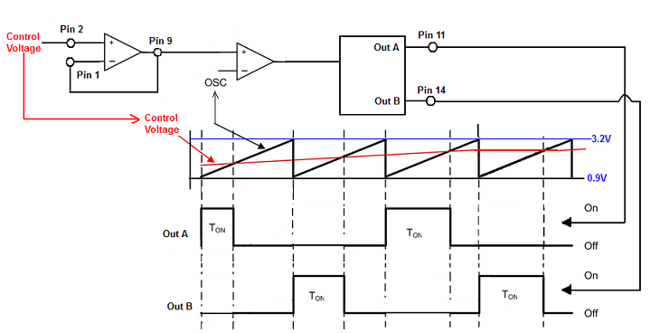
Now back to SG3525.IC's has the internal sawtooth oscillator. And And you can set the oscillator frequency by choosing thecorresponding values for RT resistor and Ct capacitor. And And the output waveform from the oscillator is "send" to PWM comparator.
This sawtooth wave swingswings between around 0.9V and 3.2V.
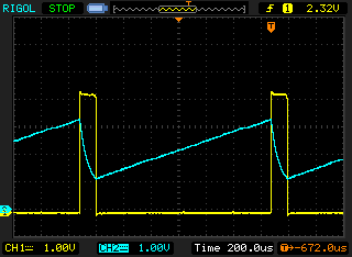
TheThis is how voltage across the Ct capacitor (pin 5) and the OSC output (pin 4) looks like in working circuit.
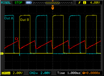
TheAnd here you have the voltage across Ct capacitor and two outputs. The Pin 11 (Out A) and Pin 14 (Out B).
The "error" signal can be applied directly to pin 9 or if you want to use the additional opamp to pin 2. But in this case, you need to connect pin 1 together with pin 9.
And kept in mind that the voltage at this pins shouldn't be larger than 5V.
Here you can find example diagram http://www.twovolt.com/wp-content/uploads/2016/07/DC-MOTOR-SPEED-CONTROLLER-1.pdf


