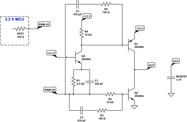
Here's a crafted design (except that I kind of ... roughed out ... the speed-up paths.) I am not worried about base oscillation of cascode \$Q_3\$ here, so I didn't do anything for it. It should be fine. If it turns out to be a problem, insert a \$68\:\Omega\$ to \$220\:\Omega\$ resistor between the base of \$Q_3\$ and the \$3.3\:\text{V}\$ supply rail.


simulate this circuitsimulate this circuit – Schematic created using CircuitLab
Worst case dissipation of any of the BJTs is probably under \$50\:\text{mW}\$, so they should be fine in open air as TO-92s. Perhaps a \$10^\circ\text{C}\$ rise?
Not shown, but probably needed will be some bypass capacitance -- I'd start with \$100\:\mu\text{F}\$ -- across the emitters of \$Q_1\$ and \$Q_2\$. Use short wiring, keep it tight, and probably use dead-bug style wiring.
Rise and fall times, of the circuit itself, can be kept near \$200\:\text{ns}\$, I believe. I would not expect worse than \$350\:\text{ns}\$, even with junk box parts. However, your MCU will have something to say about it as it's own I/O will slew at a rate of its own, too. But the edges are usually reasonably fast. I suspect this circuit will match up nicely.

