added 102 characters in body
Source Link

I needed to build a delay circuit so I'm following this guide: http://www.learningaboutelectronics.com/Articles/555-timer-delay-before-turn-on-circuit.php
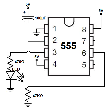
schematic

Using this circuit, I get a delay of about 5 seconds before the LED turns on. The only big difference is the output of the 555 is going into the gate of a IRFZ44N MOSFET as I needed more power.

The MOSFET source is hooked to ground, and the drain is hooked to a 330 Ohm resistor -> LED -> 5V.

However, with 5V input voltage, I can only get 3V across the drain and source. How could I improve this circuit to give me more efficiency, closer to my 5V?

EDIT: I'm following the schematic from the guide. It's exhibiting the same behavior as the guide, so the timing circuit should be correct. The only difference is the MOSFET. I also added a 330 Ohm resistor between the 555 pin 3 output and MOSFET gate and now I'm getting full voltage from drain. Looks like the gate was leeching some voltage.

I needed to build a delay circuit so I'm following this guide: http://www.learningaboutelectronics.com/Articles/555-timer-delay-before-turn-on-circuit.php

schematic

Using this circuit, I get a delay of about 5 seconds before the LED turns on. The only big difference is the output of the 555 is going into the gate of a IRFZ44N MOSFET as I needed more power.

The MOSFET source is hooked to ground, and the drain is hooked to a 330 Ohm resistor -> LED -> 5V.

However, with 5V input voltage, I can only get 3V across the drain and source. How could I improve this circuit to give me more efficiency, closer to my 5V?

EDIT: I'm following the schematic from the guide. It's exhibiting the same behavior as the guide, so the timing circuit should be correct. The only difference is the MOSFET. I also added a 330 Ohm resistor between the 555 output and MOSFET gate and now I'm getting full voltage from drain. Looks like the gate was leeching some voltage.

I needed to build a delay circuit so I'm following this guide: http://www.learningaboutelectronics.com/Articles/555-timer-delay-before-turn-on-circuit.php

schematic

Using this circuit, I get a delay of about 5 seconds before the LED turns on. The only big difference is the output of the 555 is going into the gate of a IRFZ44N MOSFET as I needed more power.

The MOSFET source is hooked to ground, and the drain is hooked to a 330 Ohm resistor -> LED -> 5V.

However, with 5V input voltage, I can only get 3V across the drain and source. How could I improve this circuit to give me more efficiency, closer to my 5V?

EDIT: I'm following the schematic from the guide. It's exhibiting the same behavior as the guide, so the timing circuit should be correct. The only difference is the MOSFET. I also added a 330 Ohm resistor between the 555 pin 3 output and MOSFET gate and now I'm getting full voltage from drain. Looks like the gate was leeching some voltage.

added 102 characters in body
Source Link

I needed to build a delay circuit so I'm following this guide: http://www.learningaboutelectronics.com/Articles/555-timer-delay-before-turn-on-circuit.php

schematic

Using this circuit, I get a delay of about 5 seconds before the LED turns on. The only big difference is the output of the 555 is going into the gate of a IRFZ44N MOSFET as I needed more power.

The MOSFET source is hooked to ground, and the drain is hooked to a 330 Ohm resistor -> LED -> 5V.

However, with 5V input voltage, I can only get 3V across the drain and source. How could I improve this circuit to give me more efficiency, closer to my 5V?

AlsoEDIT: I'm following the schematic from the guide. It's exhibiting the same behavior as the guide, so the timing circuit should be correct. The only difference is the MOSFET. I also added a 330 Ohm resistor between the power and 555 to limit drawoutput and MOSFET gate and now I'm getting full voltage from drain. Looks like the 555, but I don't think that does much, as it's 3V either waygate was leeching some voltage.

I needed to build a delay circuit so I'm following this guide: http://www.learningaboutelectronics.com/Articles/555-timer-delay-before-turn-on-circuit.php

schematic

Using this circuit, I get a delay of about 5 seconds before the LED turns on. The only big difference is the output of the 555 is going into the gate of a IRFZ44N MOSFET as I needed more power.

However, with 5V input voltage, I can only get 3V across the drain and source. How could I improve this circuit to give me more efficiency, closer to my 5V?

Also, I added a 330 Ohm resistor between the power and 555 to limit draw from the 555, but I don't think that does much, as it's 3V either way.

I needed to build a delay circuit so I'm following this guide: http://www.learningaboutelectronics.com/Articles/555-timer-delay-before-turn-on-circuit.php

schematic

Using this circuit, I get a delay of about 5 seconds before the LED turns on. The only big difference is the output of the 555 is going into the gate of a IRFZ44N MOSFET as I needed more power.

The MOSFET source is hooked to ground, and the drain is hooked to a 330 Ohm resistor -> LED -> 5V.

However, with 5V input voltage, I can only get 3V across the drain and source. How could I improve this circuit to give me more efficiency, closer to my 5V?

EDIT: I'm following the schematic from the guide. It's exhibiting the same behavior as the guide, so the timing circuit should be correct. The only difference is the MOSFET. I also added a 330 Ohm resistor between the 555 output and MOSFET gate and now I'm getting full voltage from drain. Looks like the gate was leeching some voltage.

deleted 54 characters in body
Source Link

circuit

Hello, I needed to build a delay circuit so I'm following this guide: http://www.learningaboutelectronics.com/Articles/555-timer-delay-before-turn-on-circuit.php

schematic

Using this circuit, I get a delay of about 5 seconds before the LED turns on. The only big difference is the output of the 555 is going into the gate of a IRFZ44N MOSFET as I needed more power.

However, with 5V input voltage, I can only get 3V across the drain and source. How could I improve this circuit to give me more efficiency, closer to my 5V?

Also, I added a 330 Ohm resistor between the power and 555 to limit draw from the 555, but I don't think that does much, as it's 3V either way.

I needed to build a delay circuit so I'm following this guide: http://www.learningaboutelectronics.com/Articles/555-timer-delay-before-turn-on-circuit.php

schematic

Using this circuit, I get a delay of about 5 seconds before the LED turns on. The only big difference is the output of the 555 is going into the gate of a IRFZ44N MOSFET as I needed more power.

However, with 5V input voltage, I can only get 3V across the drain and source. How could I improve this circuit to give me more efficiency, closer to my 5V?

Also, I added a 330 Ohm resistor between the power and 555 to limit draw from the 555, but I don't think that does much, as it's 3V either way.

Source Link
Loading