Tweeted twitter.com/StackElectronix/status/995975309055930370
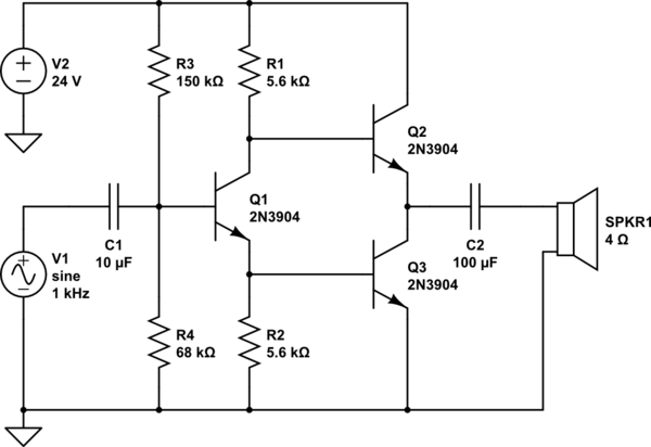
Added decoupling capacitor in front of speaker.
Source Link
Willis Blackburn
  • 1.2k
  • 1
  • 14
  • 25

In an earlier question I asked about driving a speaker with a BJT transistor. @Jonk offered a push-pull amplifier design of his own, and @G36 noted its similarity to the JLH amplifier described in a paper from 1969.

In 1969 NPN power transistors were easier to come by than PNPs, so the JLH amplifier, and @Jonk's amplifier, use two NPN transistors instead of an NPN and a PNP. This is interesting to me because I'm trying to understand tube guitar amplifiers, and tubes are more or less NPNs. (I know they're more like FETs, but my point is, there are no PNP-like tubes.)

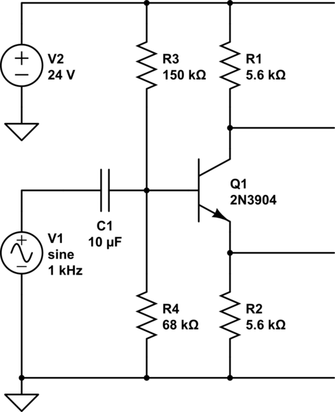
Using two NPNs requires a third NPN to act as a phase splitter. I've set this up, and it works fine:
schematic

simulate this circuit – Schematic created using CircuitLab

The base of Q1 is biased to about 6.7V (give or take). The input swings +/-5V because it is the output of a previous voltage-amplifying stage. With no signal the emitter is at 6V and and the collector at 18V, giving plenty of room the voltage swings.

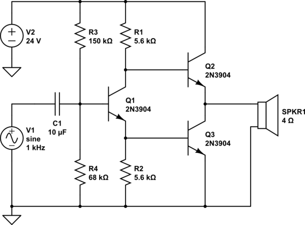
The problem is that when I attach the power NPNs, there is a zero-resistance path between the base of Q1 and ground, and all the current drains out. :-(
schematicschematic

simulate this circuitsimulate this circuit

How can this be made to work? All the examples I've seen have the emitter of the "bottom" NPN (Q3 in this case) connected to ground. But that means its base will be at about 0.7V, and the base of Q1 will be 1.4V, and they will not be able to swing +/-5V, or at all.

In the JLH and @Jonk amplifiers, there is a PNP upstream of the phase-splitter transistor that I suspect has something to do with the solution, but just can't figure out how it works.

UPDATED: Added a decoupling capacitor in front of the speaker.

In an earlier question I asked about driving a speaker with a BJT transistor. @Jonk offered a push-pull amplifier design of his own, and @G36 noted its similarity to the JLH amplifier described in a paper from 1969.

In 1969 NPN power transistors were easier to come by than PNPs, so the JLH amplifier, and @Jonk's amplifier, use two NPN transistors instead of an NPN and a PNP. This is interesting to me because I'm trying to understand tube guitar amplifiers, and tubes are more or less NPNs. (I know they're more like FETs, but my point is, there are no PNP-like tubes.)

Using two NPNs requires a third NPN to act as a phase splitter. I've set this up, and it works fine:

schematic

simulate this circuit – Schematic created using CircuitLab

The base of Q1 is biased to about 6.7V (give or take). The input swings +/-5V because it is the output of a previous voltage-amplifying stage. With no signal the emitter is at 6V and and the collector at 18V, giving plenty of room the voltage swings.

The problem is that when I attach the power NPNs, there is a zero-resistance path between the base of Q1 and ground, and all the current drains out. :-(

schematic

simulate this circuit

How can this be made to work? All the examples I've seen have the emitter of the "bottom" NPN (Q3 in this case) connected to ground. But that means its base will be at about 0.7V, and the base of Q1 will be 1.4V, and they will not be able to swing +/-5V, or at all.

In the JLH and @Jonk amplifiers, there is a PNP upstream of the phase-splitter transistor that I suspect has something to do with the solution, but just can't figure out how it works.

UPDATED: Added a decoupling capacitor in front of the speaker.

Source Link
Willis Blackburn
  • 1.2k
  • 1
  • 14
  • 25

How to keep current from draining out the bottom of this push-pull amplifier?

In an earlier question I asked about driving a speaker with a BJT transistor. @Jonk offered a push-pull amplifier design of his own, and @G36 noted its similarity to the JLH amplifier described in a paper from 1969.

In 1969 NPN power transistors were easier to come by than PNPs, so the JLH amplifier, and @Jonk's amplifier, use two NPN transistors instead of an NPN and a PNP. This is interesting to me because I'm trying to understand tube guitar amplifiers, and tubes are more or less NPNs. (I know they're more like FETs, but my point is, there are no PNP-like tubes.)

Using two NPNs requires a third NPN to act as a phase splitter. I've set this up, and it works fine:

schematic

simulate this circuit – Schematic created using CircuitLab

The base of Q1 is biased to about 6.7V (give or take). The input swings +/-5V because it is the output of a previous voltage-amplifying stage. With no signal the emitter is at 6V and and the collector at 18V, giving plenty of room the voltage swings.

The problem is that when I attach the power NPNs, there is a zero-resistance path between the base of Q1 and ground, and all the current drains out. :-(

schematic

simulate this circuit

How can this be made to work? All the examples I've seen have the emitter of the "bottom" NPN (Q3 in this case) connected to ground. But that means its base will be at about 0.7V, and the base of Q1 will be 1.4V, and they will not be able to swing +/-5V, or at all.

In the JLH and @Jonk amplifiers, there is a PNP upstream of the phase-splitter transistor that I suspect has something to do with the solution, but just can't figure out how it works.