edited body
Source Link
jonk
  • 78.8k
  • 6
  • 81
  • 195
added 401 characters in body
Source Link
jonk
  • 78.8k
  • 6
  • 81
  • 195

schematicschematic

simulate this circuitsimulate this circuit


Update

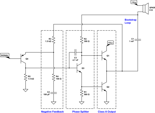
I updated the final schematic above. I'd completely forgotten about the need to force a high frequency roll-off. I've added \$C_3\$ with a nominal value that is reasonably placed, I think. The Ohmic resistances in \$Q_1\$ and \$Q_2\$ should also be put under management and current limiting would be useful, too. But that compensation pole is a must. So it's added now.

schematic

simulate this circuit


Update

I updated the final schematic above. I'd completely forgotten about the need to force a high frequency roll-off. I've added \$C_3\$ with a nominal value that is reasonably placed, I think. The Ohmic resistances in \$Q_1\$ and \$Q_2\$ should also be put under management and current limiting would be useful, too. But that compensation pole is a must. So it's added now.

deleted 184 characters in body
Source Link
jonk
  • 78.8k
  • 6
  • 81
  • 195

From the earlier design step we have \$30\:\text{mVpp}\$ for \$Q_2\$. But we also need to account for the fact that there will also beI'd selected this operating point by completely ignoring the same \$30\:\text{mVpp}\$ variation at \$Q_1\$'s \$V_\text{BE}\$, here exactly out of phaseOhmic resistances. Because of the phase and the magnitudeThese matter. For now, this leads to just exactly enough variation in the current in \$R_2\$ and inI'm just going to randomly double the right direction, that it doubles thisearlier estimated variation over \$R_2\$. So we actually should expect to see about \$60\:\text{mVpp}\$ variation over \$R_1\$.

What about the base of \$Q_3\$? Well, we also must expectExpect another \$30\:\text{mVpp}\$ to be added to the already expectednow planned \$60\:\text{mVpp}\$ for (since\$Q_2\$. (\$Q_3\$'s collector current is going through similar variations.) So that means close to, rounded up, about \$100\:\text{mVpp}\$ for the base of \$Q_3\$ as a reasoned plan.

That'sSo that's the drive for \$Q_3\$. The entire output section and splitter combined must be driven by a voltage signal that cannot vary by more than \$100\:\text{mVpp}\$. We also know that the center of this voltage must be approximately two \$V_\text{BE}\$'s, right? This means \$1.4\:\text{V}\$ or thereabouts.

NOTEGain Notes

From the earlier design step we have \$30\:\text{mVpp}\$ for \$Q_2\$. But we also need to account for the fact that there will also be the same \$30\:\text{mVpp}\$ variation at \$Q_1\$'s \$V_\text{BE}\$, here exactly out of phase. Because of the phase and the magnitude, this leads to just exactly enough variation in the current in \$R_2\$ and in just the right direction, that it doubles this variation over \$R_2\$. So we actually should expect to see about \$60\:\text{mVpp}\$ variation over \$R_1\$.

What about the base of \$Q_3\$? Well, we also must expect another \$30\:\text{mVpp}\$ to be added to the already expected \$60\:\text{mVpp}\$ (since \$Q_3\$'s collector current is going through similar variations.) So that means close to \$100\:\text{mVpp}\$ for the base of \$Q_3\$.

That's the drive for \$Q_3\$. The entire output section and splitter combined must be driven by a voltage signal that cannot vary by more than \$100\:\text{mVpp}\$. We also know that the center of this voltage must be approximately two \$V_\text{BE}\$'s, right? This means \$1.4\:\text{V}\$ or thereabouts.

NOTE

From the earlier design step we have \$30\:\text{mVpp}\$ for \$Q_2\$. I'd selected this operating point by completely ignoring the Ohmic resistances. These matter. For now, I'm just going to randomly double the earlier estimated variation over \$R_2\$. So about \$60\:\text{mVpp}\$ variation over \$R_1\$.

What about the base of \$Q_3\$? Expect another \$30\:\text{mVpp}\$ to be added to the now planned \$60\:\text{mVpp}\$ for \$Q_2\$. (\$Q_3\$'s collector current is going through similar variations.) So that means, rounded up, about \$100\:\text{mVpp}\$ for the base of \$Q_3\$ as a reasoned plan.

So that's the drive for \$Q_3\$. The entire output section and splitter combined must be driven by a voltage signal that cannot vary by more than \$100\:\text{mVpp}\$. We also know that the center of this voltage must be approximately two \$V_\text{BE}\$'s, right? This means \$1.4\:\text{V}\$ or thereabouts.

Gain Notes

added 641 characters in body
Source Link
jonk
  • 78.8k
  • 6
  • 81
  • 195
Loading
added 396 characters in body
Source Link
jonk
  • 78.8k
  • 6
  • 81
  • 195
Loading
added 992 characters in body
Source Link
jonk
  • 78.8k
  • 6
  • 81
  • 195
Loading
added 23 characters in body
Source Link
jonk
  • 78.8k
  • 6
  • 81
  • 195
Loading
edited body
Source Link
jonk
  • 78.8k
  • 6
  • 81
  • 195
Loading
added 4 characters in body
Source Link
jonk
  • 78.8k
  • 6
  • 81
  • 195
Loading
added 36 characters in body
Source Link
jonk
  • 78.8k
  • 6
  • 81
  • 195
Loading
added 36 characters in body
Source Link
jonk
  • 78.8k
  • 6
  • 81
  • 195
Loading
added 36 characters in body
Source Link
jonk
  • 78.8k
  • 6
  • 81
  • 195
Loading
Source Link
jonk
  • 78.8k
  • 6
  • 81
  • 195
Loading