Copy edited (e.g. ref. <http://www.wikihow.com/Use-You%27re-and-Your> and <https://en.wikipedia.org/wiki/Ohm>).
Source Link
Voltage Spike
  • 88.9k
  • 49
  • 90
  • 234

A CAN bus is meant to be an (electrically) straight line with a terminator at each end and nodes (at least two) attached along it. That means just two terminators.

If you're willing to give up some length and/or noise margin are not of concern, you can add some stubs out to nodes can be added. As long as they’re short, they don’t hurt too much. One imperfect heuristic is to take twice the length of the stub away from the possible total length; a coarse approximation, but a starting point.

A node looks like a 10 kohm (or more) load on the bus. If you attach extra terminators, i.e. more than the required two, near the center of the bus, that adds a lot more load (about 100 times as much current), so it greatly reduces how many nodes you can attach to the bus. One extra probably will still work, but might not handle noise well. Two or more extra terminators (i.e. 4 total) are unlikely to work.

With three nodes close together, almost any wiring will work, so don’t worry about stub wiring too much. Just put two terminators on, one at each nominal end, and enjoy.
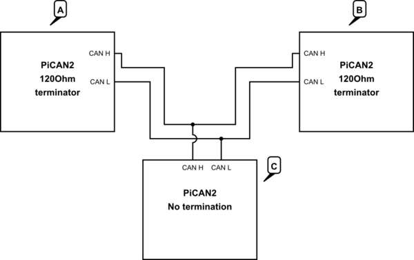
Schematic

simulate this circuit – Schematic created using CircuitLab

A CAN bus is meant to be an (electrically) straight line with a terminator at each end and nodes (at least two) attached along it. That means just two terminators.

If you're willing to give up some length and/or noise margin, you can add some stubs out to nodes. As long as they’re short, they don’t hurt too much. One imperfect heuristic is to take twice the length of the stub away from the possible total length; a coarse approximation, but a starting point.

A node looks like a 10 kohm (or more) load on the bus. If you attach extra terminators, i.e. more than the required two, near the center of the bus, that adds a lot more load (about 100 times as much current), so it greatly reduces how many nodes you can attach to the bus. One extra probably will still work, but might not handle noise well. Two or more extra terminators (i.e. 4 total) are unlikely to work.

With three nodes close together, almost any wiring will work, so don’t worry about stub wiring too much. Just put two terminators on, one at each nominal end, and enjoy.

Schematic

simulate this circuit – Schematic created using CircuitLab

A CAN bus is meant to be an (electrically) straight line with a terminator at each end and nodes (at least two) attached along it. That means just two terminators.

If length and/or noise margin are not of concern, some stubs out to nodes can be added. As long as they’re short, they don’t hurt too much. One imperfect heuristic is to take twice the length of the stub away from the possible total length; a coarse approximation, but a starting point.

A node looks like a 10 kohm (or more) load on the bus. If you attach extra terminators, i.e. more than the required two, near the center of the bus, that adds a lot more load (about 100 times as much current), so it greatly reduces how many nodes you can attach to the bus. One extra probably will still work, but might not handle noise well. Two or more extra terminators (i.e. 4 total) are unlikely to work.

With three nodes close together, almost any wiring will work, so don’t worry about stub wiring too much. Just put two terminators on, one at each nominal end, and enjoy.

Schematic

simulate this circuit – Schematic created using CircuitLab

Copy edited (e.g. ref. <http://www.wikihow.com/Use-You%27re-and-Your> and <https://en.wikipedia.org/wiki/Ohm>).
Source Link

A CAN bus is meant to be an (electrically) straight line with a terminator at each end and nodes (at least two) attached along it. That means just two terminators.

If youryou're willing to give up some length and/or noise margin, you can add some stubs out to nodes. As long as they’re short, they don’t hurt too much. One imperfect heuristic is to take twice the length of the stub away from the possible total length; a coarse approximation, but a starting point.

A node looks like a 10kOhm10 kohm (or more) load on the bus. If you attach an extra terminators, i.e. more than the required two, near the center of the bus, that adds a lot more load (about 100 times as much current), so it greatly reduces how many nodes you can attach to the bus. One extra probably will still work, but might not handle noise well. TwoTwo or more extra terminators (i.e. 4 total) are unlikely to work.

With three nodes close together, almost any wiring will work, so don’t worry about stub wiring too much. Just put two terminators on, one at each nominal end, and enjoy.

schematicSchematic

simulate this circuit – Schematic created using CircuitLab

A CAN bus is meant to be an (electrically) straight line with a terminator at each end and nodes (at least two) attached along it. That means just two terminators.

If your willing to give up some length and/or noise margin, you can add some stubs out to nodes. As long as they’re short, they don’t hurt too much. One imperfect heuristic is to take twice the length of the stub away from the possible total length; a coarse approximation but a starting point.

A node looks like a 10kOhm (or more) load on the bus. If you attach an extra terminators, i.e. more than the required two, near the center of the bus, that adds a lot more load (about 100 times as much current), so it greatly reduces how many nodes you can attach to the bus. One extra probably will still work, but might not handle noise well. Two or more extra terminators (i.e. 4 total) are unlikely to work.

With three nodes close together, almost any wiring will work, so don’t worry about stub wiring too much. Just put two terminators on, one at each nominal end, and enjoy.

schematic

simulate this circuit – Schematic created using CircuitLab

A CAN bus is meant to be an (electrically) straight line with a terminator at each end and nodes (at least two) attached along it. That means just two terminators.

If you're willing to give up some length and/or noise margin, you can add some stubs out to nodes. As long as they’re short, they don’t hurt too much. One imperfect heuristic is to take twice the length of the stub away from the possible total length; a coarse approximation, but a starting point.

A node looks like a 10 kohm (or more) load on the bus. If you attach extra terminators, i.e. more than the required two, near the center of the bus, that adds a lot more load (about 100 times as much current), so it greatly reduces how many nodes you can attach to the bus. One extra probably will still work, but might not handle noise well. Two or more extra terminators (i.e. 4 total) are unlikely to work.

With three nodes close together, almost any wiring will work, so don’t worry about stub wiring too much. Just put two terminators on, one at each nominal end, and enjoy.

Schematic

simulate this circuit – Schematic created using CircuitLab

added 263 characters in body
Source Link
Bob Jacobsen
  • 1.9k
  • 1
  • 11
  • 10

A CAN bus is meant to be an (electrically) straight line with a terminator at each end and nodes (at least two) attached along it. That means just two terminators.

If your willing to give up some length and/or noise margin, you can add some stubs out to nodes. As long as they’re short, they don’t hurt too much. One imperfect heuristic is to take twice the length of the stub away from the possible total length; a coarse approximation but a starting point.

ExtraA node looks like a 10kOhm (or more) load on the bus. If you attach an extra terminators, especiallyi.e. more than the required two, near the center of the bus, havethat adds a lot more of an effect of the maximum number ofload (about 100 times as much current), so it greatly reduces how many nodes beforeyou can attach to the bus. One extra probably will still work, but might not handle noise sensitivity gets poorwell. Two or more extra terminators (i.e. 4 total) are unlikely to work.

With three nodes close together, almost anythingany wiring will work, though, so don’t worry about thisstub wiring too much. Just put two terminators on, one at each nominal end, and enjoy.

schematic

simulate this circuit – Schematic created using CircuitLab

A CAN bus is meant to be an (electrically) straight line with a terminator at each end and nodes (at least two) attached along it. That means just two terminators.

If your willing to give up some length and/or noise margin, you can add some stubs out to nodes. As long as they’re short, they don’t hurt too much. One imperfect heuristic is to take twice the length of the stub away from the possible total length; a coarse approximation but a starting point.

Extra terminators, especially near the center of the bus, have more of an effect of the maximum number of nodes before noise sensitivity gets poor.

With three nodes close together, almost anything will work, though, so don’t worry about this too much. Just put two terminators on, one at each nominal end, and enjoy.

schematic

simulate this circuit – Schematic created using CircuitLab

A CAN bus is meant to be an (electrically) straight line with a terminator at each end and nodes (at least two) attached along it. That means just two terminators.

If your willing to give up some length and/or noise margin, you can add some stubs out to nodes. As long as they’re short, they don’t hurt too much. One imperfect heuristic is to take twice the length of the stub away from the possible total length; a coarse approximation but a starting point.

A node looks like a 10kOhm (or more) load on the bus. If you attach an extra terminators, i.e. more than the required two, near the center of the bus, that adds a lot more load (about 100 times as much current), so it greatly reduces how many nodes you can attach to the bus. One extra probably will still work, but might not handle noise well. Two or more extra terminators (i.e. 4 total) are unlikely to work.

With three nodes close together, almost any wiring will work, so don’t worry about stub wiring too much. Just put two terminators on, one at each nominal end, and enjoy.

schematic

simulate this circuit – Schematic created using CircuitLab

added schematic
Source Link
Loading
Source Link
Bob Jacobsen
  • 1.9k
  • 1
  • 11
  • 10
Loading