added 287 characters in body
Source Link
Henry Crun
  • 5.5k
  • 12
  • 12

What are these "transistors" of which you speak?
schematic

simulate this circuit – Schematic created using CircuitLab

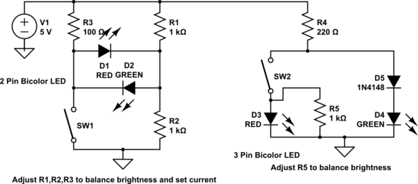
You need to adjust the resistor values to get the currents you want, and to balance the brightness of the leds, as different leds/colours have different brightnesses. (hint: you can use "simulate this circuit")

Both can be used with a single bicolor LED if you want. D4 should be a higher voltage color than D3. V(D4+D3) >> V(D3), so when SW2 closes the current goes though D3.

Note that the forward voltage of the different colors is important in these arrangements.

These arrangements work better on higher voltages, as the currents will naturally be be closer for the two leds.


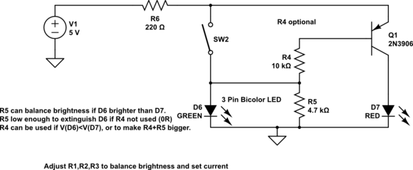
Oh, alright here's a transistor one. It's a better choice at low voltages, it can give nearly equal currents on 3.3V. R6 sets the LED current. If you use R4 and R5, then the voltage across D6 is <1V, and the D6 off current is very small.

The lower Von RED led is paired with the transistor so the voltage of both paths is more equal.
schematic

simulate this circuit

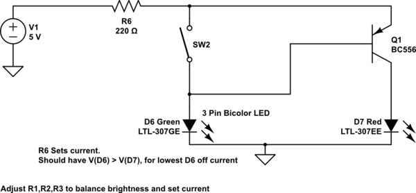
As long as Q1 has reasonable gain, neither resistor is really needed, as the off current of D6 is only 100-200uA. The more D6.Von (green) is > D7.Von (red), the less the off current will be. This arrangement works if D6=blue, D7=red, but you need R4,5 if D& blue, D6 red.
schematic

simulate this circuit

So if your switch has to have one end connected to the battery, you just move R6, and flip it all over if you want (-ve) switch.
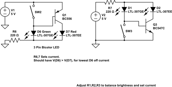
schematic

simulate this circuit

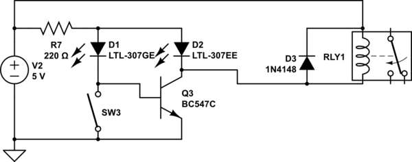
Adding a relay...

schematic

simulate this circuit

What are these "transistors" of which you speak?

schematic

simulate this circuit – Schematic created using CircuitLab

You need to adjust the resistor values to get the currents you want, and to balance the brightness of the leds, as different leds/colours have different brightnesses. (hint: you can use "simulate this circuit")

Both can be used with a single bicolor LED if you want. D4 should be a higher voltage color than D3. V(D4+D3) >> V(D3), so when SW2 closes the current goes though D3.

Note that the forward voltage of the different colors is important in these arrangements.

These arrangements work better on higher voltages, as the currents will naturally be be closer for the two leds.


Oh, alright here's a transistor one. It's a better choice at low voltages, it can give nearly equal currents on 3.3V. R6 sets the LED current. If you use R4 and R5, then the voltage across D6 is <1V, and the D6 off current is very small.

The lower Von RED led is paired with the transistor so the voltage of both paths is more equal.

schematic

simulate this circuit

As long as Q1 has reasonable gain, neither resistor is really needed, as the off current of D6 is only 100-200uA. The more D6.Von (green) is > D7.Von (red), the less the off current will be. This arrangement works if D6=blue, D7=red, but you need R4,5 if D& blue, D6 red.

schematic

simulate this circuit

So if your switch has to have one end connected to the battery, you just move R6, and flip it all over if you want (-ve) switch.

schematic

simulate this circuit

Adding a relay...

schematic

simulate this circuit

added 396 characters in body
Source Link
Henry Crun
  • 5.5k
  • 12
  • 12

What are these "transistors" of which you speak?

schematic

simulate this circuit – Schematic created using CircuitLab

You need to adjust the resistor values to get the currents you want, and to balance the brightness of the leds, as different leds/colours have different brightnesses. (hint: you can use "simulate this circuit")

Both can be used with a single bicolor LED if you want. D4 should be a higher voltage color than D3. V(D4+D3) >> V(D3), so when SW2 closes the current goes though D3.

Note that the forward voltage of the different colors is important in these arrangements.

These arrangements work better on higher voltages, as the currents will naturally be be closer for the two leds.


Oh, alright here's a transistor one. It's a better choice at low voltages, it can give nearly equal currents on 3.3V. R6 sets the LED current. If you use R4 and R5, then the voltage across D6 is <1V, and the D6 off current is very small.

The lower Von RED led is paired with the transistor so the voltage of both paths is more equal.

schematic

simulate this circuit

As long as Q1 has reasonable gain, neither resistor is really needed, as the off current of D6 is only 100-200uA. The more D6.Von (green) is > D7.Von (red), the less the off current will be. This arrangement works if D6=blue, D7=red, but you need R4,5 if D& blue, D6 red.

schematic

simulate this circuit

So if your switch has to have one end connected to the battery, you just move R6, and flip it all over if you want (-ve) switch.

schematicschematic

simulate this circuitsimulate this circuit

What are these "transistors" of which you speak?

schematic

simulate this circuit – Schematic created using CircuitLab

You need to adjust the resistor values to get the currents you want, and to balance the brightness of the leds, as different leds/colours have different brightnesses. (hint: you can use "simulate this circuit")

Both can be used with a single bicolor LED if you want. D4 should be a higher voltage color than D3. V(D4+D3) >> V(D3), so when SW2 closes the current goes though D3.

Note that the forward voltage of the different colors is important in these arrangements.

These arrangements work better on higher voltages, as the currents will naturally be be closer for the two leds.


Oh, alright here's a transistor one. It's a better choice at low voltages, it can give nearly equal currents on 3.3V. R6 sets the LED current. If you use R4 and R5, then the voltage across D6 is <1V, and the D6 off current is very small.

The lower Von RED led is paired with the transistor so the voltage of both paths is more equal.

schematic

simulate this circuit

As long as Q1 has reasonable gain, neither resistor is really needed, as the off current of D6 is only 100-200uA. The more D6.Von (green) is > D7.Von (red), the less the off current will be. This arrangement works if D6=blue, D7=red, but you need R4,5 if D& blue, D6 red.

schematic

simulate this circuit

So if your switch has to have one end connected to the battery, you just move R6, and flip it all over if you want (-ve) switch.

schematic

simulate this circuit

added 396 characters in body
Source Link
Henry Crun
  • 5.5k
  • 12
  • 12

What are these "transistors" of which you speak?

schematic

simulate this circuit – Schematic created using CircuitLab

You need to adjust the resistor values to get the currents you want, and to balance the brightness of the leds, as different leds/colours have different brightnesses. (hint: you can use "simulate this circuit")

Both can be used with a single bicolor LED if you want. D4 should be a higher voltage color than D3. V(D4+D3) >> V(D3), so when SW2 closes the current goes though D3.

Note that the forward voltage of the different colors is important in these arrangements.

These arrangements work better on higher voltages, as the currents will naturally be be closer for the two leds.


Oh, alright here's a transistor one. It's a better choice at low voltages, it can give nearly equal currents on 3.3V. R6 sets the LED current. If you use R4 and R5, then the voltage across D6 is <1V, and the D6 off current is very small.

The lower Von RED led is paired with the transistor so the voltage of both paths is more equal.

schematic

simulate this circuit

As long as Q1 has reasonable gain, neither resistor is really needed, as the off current of D6 is only 100-200uA. The more D6.Von (green) is > D7.Von (red), the less the off current will be. This arrangement works if D6=blue, D7=red, but you need R4,5 if D& blue, D6 red.

schematic

simulate this circuit

So if your switch has to have one end connected to the battery, you just move R6, and flip it all over if you want (-ve) switch.

schematic

simulate this circuit

What are these "transistors" of which you speak?

schematic

simulate this circuit – Schematic created using CircuitLab

You need to adjust the resistor values to get the currents you want, and to balance the brightness of the leds, as different leds/colours have different brightnesses. (hint: you can use "simulate this circuit")

Both can be used with a single bicolor LED if you want. D4 should be a higher voltage color than D3. V(D4+D3) >> V(D3), so when SW2 closes the current goes though D3.

Note that the forward voltage of the different colors is important in these arrangements.

These arrangements work better on higher voltages, as the currents will naturally be be closer for the two leds.


Oh, alright here's a transistor one. It's a better choice at low voltages, it can give nearly equal currents on 3.3V. R6 sets the LED current. If you use R4 and R5, then the voltage across D6 is <1V, and the D6 off current is very small.

The lower Von RED led is paired with the transistor so the voltage of both paths is more equal.

schematic

simulate this circuit

As long as Q1 has reasonable gain, neither resistor is really needed, as the off current of D6 is only 100-200uA. The more D6.Von (green) is > D7.Von (red), the less the off current will be. This arrangement works if D6=blue, D7=red, but you need R4,5 if D& blue, D6 red.

schematic

simulate this circuit

So if your switch has to have one end connected to the battery, you just move R6, and flip it all over if you want (-ve) switch.

schematic

simulate this circuit

added 374 characters in body
Source Link
Henry Crun
  • 5.5k
  • 12
  • 12
Loading
added 374 characters in body
Source Link
Henry Crun
  • 5.5k
  • 12
  • 12
Loading
added 374 characters in body
Source Link
Henry Crun
  • 5.5k
  • 12
  • 12
Loading
edited body
Source Link
Henry Crun
  • 5.5k
  • 12
  • 12
Loading
added 45 characters in body
Source Link
Henry Crun
  • 5.5k
  • 12
  • 12
Loading
added 490 characters in body
Source Link
Henry Crun
  • 5.5k
  • 12
  • 12
Loading
added 481 characters in body
Source Link
Henry Crun
  • 5.5k
  • 12
  • 12
Loading
added 481 characters in body
Source Link
Henry Crun
  • 5.5k
  • 12
  • 12
Loading
Source Link
Henry Crun
  • 5.5k
  • 12
  • 12
Loading