added 79 characters in body
Source Link
Passerby
  • 73.4k
  • 7
  • 95
  • 212

Your circuit is mostly correct. The common would be the 12V keyed voltage source (do not connect it to the battery directly unless you like paying for new ones weekly). The normally closed would be the DRL, and the normally opened the flasher circuit. You'd need one that can deal with the low currents of an LED strip.

The control switch and "in" is where your circuit isn't accurate. Most common relays do not have a separate input from the positive and negative poles of the coil. The switch would be in line with the relay coil power (before or after, does not matter). Plus add an inline Fuse for safety (1 to 2.5 amp would be fine). That's the only change.
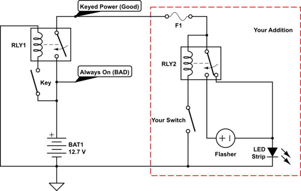
schematic

simulate this circuit – Schematic created using CircuitLab

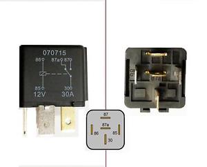
Typical automotive relay:
enter image description here

Alternatively, there are flasher modules that include the relay, so no separate relay is needed.

Your circuit is mostly correct. The common would be the 12V keyed voltage source (do not connect it to the battery directly unless you like paying for new ones weekly). The normally closed would be the DRL, and the normally opened the flasher circuit. You'd need one that can deal with the low currents of an LED strip.

The control switch and "in" is where your circuit isn't accurate. Most common relays do not have a separate input from the positive and negative poles of the coil. The switch would be in line with the relay coil power. Plus an inline Fuse. That's the only change.

schematic

simulate this circuit – Schematic created using CircuitLab

Typical automotive relay:
enter image description here

Alternatively, there are flasher modules that include the relay, so no separate relay is needed.
Your circuit is mostly correct. The common would be the 12V keyed voltage source (do not connect it to the battery directly unless you like paying for new ones weekly). The normally closed would be the DRL, and the normally opened the flasher circuit. You'd need one that can deal with the low currents of an LED strip.

The control switch and "in" is where your circuit isn't accurate. Most common relays do not have a separate input from the positive and negative poles of the coil. The switch would be in line with the relay coil power (before or after, does not matter). Plus add an inline Fuse for safety (1 to 2.5 amp would be fine). That's the only change.

schematic

simulate this circuit – Schematic created using CircuitLab

Typical automotive relay:
enter image description here

Alternatively, there are flasher modules that include the relay, so no separate relay is needed.

added 511 characters in body
Source Link
Passerby
  • 73.4k
  • 7
  • 95
  • 212

Your circuit is mostly correct. The common would be the 12V keyed voltage source (do not connect it to the battery directly unless you like paying for new ones weekly). The normally closed would be the DRL, and the normally opened the flasher circuit. You'd need one that can deal with the low currents of an LED strip.

The control switch and "in" is where your circuit isn't accurate. Most common relays do not have a separate input from the positive and negative poles of the coil. The switch would be in line with the relay coil power. Plus an inline Fuse. That's the only change.

schematic

simulate this circuit – Schematic created using CircuitLab

Typical automotive relay:
enter image description here

Alternatively, there are flasher modules that include the relay, so no separate relay is needed.

Your circuit is mostly correct. The common would be the 12V keyed voltage source (do not connect it to the battery directly unless you like paying for new ones weekly). The normally closed would be the DRL, and the normally opened the flasher circuit. You'd need one that can deal with the low currents of an LED strip.

The control switch and "in" is where your circuit isn't accurate. Most common relays do not have a separate input from the positive and negative poles of the coil. The switch would be in line with the relay coil power. That's the only change.

Your circuit is mostly correct. The common would be the 12V keyed voltage source (do not connect it to the battery directly unless you like paying for new ones weekly). The normally closed would be the DRL, and the normally opened the flasher circuit. You'd need one that can deal with the low currents of an LED strip.

The control switch and "in" is where your circuit isn't accurate. Most common relays do not have a separate input from the positive and negative poles of the coil. The switch would be in line with the relay coil power. Plus an inline Fuse. That's the only change.

schematic

simulate this circuit – Schematic created using CircuitLab

Typical automotive relay:
enter image description here

Alternatively, there are flasher modules that include the relay, so no separate relay is needed.

Source Link
Passerby
  • 73.4k
  • 7
  • 95
  • 212

Your circuit is mostly correct. The common would be the 12V keyed voltage source (do not connect it to the battery directly unless you like paying for new ones weekly). The normally closed would be the DRL, and the normally opened the flasher circuit. You'd need one that can deal with the low currents of an LED strip.

The control switch and "in" is where your circuit isn't accurate. Most common relays do not have a separate input from the positive and negative poles of the coil. The switch would be in line with the relay coil power. That's the only change.