added 988 characters in body
Source Link
jonk
  • 78.7k
  • 6
  • 81
  • 195

The same topology shown above can also be made to work with MOSFETs:
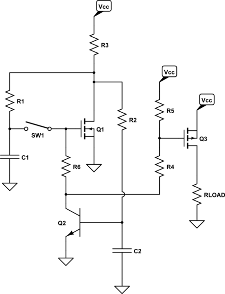
schematic

simulate this circuit

In the above case, \$R_3\$ can be made very much larger and this can greatly reduce the quiescent current (holding) for the OFF state of the switch. (The circuit still depends upon \$Q_1\$ being ON and \$Q_2\$ being OFF, when quiescent/OFF, so this means that your supply voltage will be across \$R_3\$ in this state.)

Circuit details such as parasitics and worsening saturation beta for \$Q_2\$ at very low collector currents will be the limitation. I would say that designing around about \$10\:\mu\text{A}\$ would be easily achievable without such considerations. And that less might be had, with some thought to them.

deleted 109 characters in body
Source Link
jonk
  • 78.7k
  • 6
  • 81
  • 195

My intuition tells me that the use of a single capacitor as two-state memory for this purpose makes the problem more difficult. Even with the use of MOSFETs. I think for stability and perhaps even simplicity's sake, I'd start out trying two capacitors. (I often use a MOSFET+BJT with one capacitor for a timed on-period, though, where the MOSFET+RC is vital to stay truer to the RC timing assumption.) One of them to ensure a consistent power-on state.

My intuition tells me that the use of a single capacitor as two-state memory for this purpose makes the problem more difficult. Even with the use of MOSFETs. I think for stability and perhaps even simplicity's sake, I'd start out trying two capacitors. (I often use a MOSFET+BJT with one capacitor for a timed on-period, though, where the MOSFET+RC is vital to stay truer to the RC timing assumption.)

I think for stability and perhaps even simplicity's sake, I'd start out trying two capacitors. (I often use a MOSFET+BJT with one capacitor for a timed on-period, though, where the MOSFET+RC is vital to stay truer to the RC timing assumption.) One of them to ensure a consistent power-on state.

added 92 characters in body
Source Link
jonk
  • 78.7k
  • 6
  • 81
  • 195

(This assumes the current arriving at the base of \$Q_1\$ via \$R_5\$, \$R_4\$, and \$R_6\$ isn't sufficient to cause a voltage drop across \$R_5\$ that would turn \$Q_3\$ ON, of course. This is easily achieved, though, because \$Q_1\$'s collector is only sinking a very modest current determined by \$R_3\$ and therefore won't need a sizeable base current via \$R_5\$. [Easily arranged to avoid turning \$Q_3\$ ON.] When \$Q_3\$ is turned ON, of course, then \$Q_2\$'s collector must sink all of the needed base current of \$Q_3\$ and that will cause a voltage drop across \$R_5\$.)

The quiescent state should arrive with only a very small voltage across \$C_1\$ and \$C_2\$ (basically, whatever the \$V_{\text{CE}_\text{SAT}}\$ of \$Q_1\$ permits, and no more than that.) So both capacitors remain discharged, to start, and \$Q_1\$ is ON (because of the path through \$R_5\$, \$R_4\$, and \$R_6\$) and \$Q_2\$ is OFF.

The quiescent state should arrive with only a very small voltage across \$C_1\$ and \$C_2\$ (basically, whatever the \$V_{\text{CE}_\text{SAT}}\$ of \$Q_1\$ permits, and no more than that.) So both capacitors remain discharged, to start, and \$Q_1\$ is ON (because of the path through \$R_5\$, \$R_4\$, and \$R_6\$) and \$Q_2\$ is OFF.

(This assumes the current arriving at the base of \$Q_1\$ via \$R_5\$, \$R_4\$, and \$R_6\$ isn't sufficient to cause a voltage drop across \$R_5\$ that would turn \$Q_3\$ ON, of course. This is easily achieved, though, because \$Q_1\$'s collector is only sinking a very modest current determined by \$R_3\$ and therefore won't need a sizeable base current via \$R_5\$. [Easily arranged to avoid turning \$Q_3\$ ON.] When \$Q_3\$ is turned ON, of course, then \$Q_2\$'s collector must sink all of the needed base current of \$Q_3\$ and that will cause a voltage drop across \$R_5\$.)

The quiescent state should arrive with only a very small voltage across \$C_1\$ and \$C_2\$ (basically, whatever the \$V_{\text{CE}_\text{SAT}}\$ of \$Q_1\$ permits, and no more than that.) So both capacitors remain discharged, to start, and \$Q_1\$ is ON (because of the path through \$R_5\$, \$R_4\$, and \$R_6\$) and \$Q_2\$ is OFF.

added 92 characters in body
Source Link
jonk
  • 78.7k
  • 6
  • 81
  • 195
Loading
Source Link
jonk
  • 78.7k
  • 6
  • 81
  • 195
Loading