added 147 characters in body
Source Link
Bruce Abbott
  • 57k
  • 1
  • 49
  • 94

Figure 5-1 is a bit misleading. In fact none of the PIC10F220's I/O pin circuits look exactly like that. Here's the circuit for pin 2:-

enter image description here

Note that GP2's output driver is disabled when T0CS is high. T0CS is bit 5 of the OPTION register, and guess what? Yes, it's high at power on!

To enable digital output on pin 2 you need to clear the T0CS bit in the option register, like this:-

movlw b'11011111' ; T0CS low, other option bits high
option

If you want to use GP0 or GP1 as outputs then you have a similar problem. These pins are shared with analog inputs AN0 and AN1, which are enabled at power on. To enable their digital outputs you need to clear the ANS1 and ANS0 bits in ADCON0.

EDIT:

Your updated code simulated correctly for me in MPLab 8.92 but not in MPLabX 3.65, which suggests a bug in the MPLabX simulator.

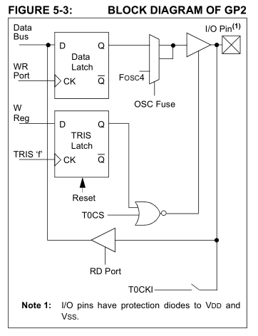
Figure 5-1 is a bit misleading. In fact none of the PIC10F220's I/O pin circuits look exactly like that. Here's the circuit for pin 2:-

enter image description here

Note that GP2's output driver is disabled when T0CS is high. T0CS is bit 5 of the OPTION register, and guess what? Yes, it's high at power on!

To enable digital output on pin 2 you need to clear the T0CS bit in the option register, like this:-

movlw b'11011111' ; T0CS low, other option bits high
option

If you want to use GP0 or GP1 as outputs then you have a similar problem. These pins are shared with analog inputs AN0 and AN1, which are enabled at power on. To enable their digital outputs you need to clear the ANS1 and ANS0 bits in ADCON0.

EDIT:

Your updated code simulated correctly for me in MPLab 8.92 but not in MPLabX 3.65, which suggests a bug in the MPLabX simulator.

Source Link
Bruce Abbott
  • 57k
  • 1
  • 49
  • 94

Figure 5-1 is a bit misleading. In fact none of the PIC10F220's I/O pin circuits look exactly like that. Here's the circuit for pin 2:-

enter image description here

Note that GP2's output driver is disabled when T0CS is high. T0CS is bit 5 of the OPTION register, and guess what? Yes, it's high at power on!

To enable digital output on pin 2 you need to clear the T0CS bit in the option register, like this:-

movlw b'11011111' ; T0CS low, other option bits high
option

If you want to use GP0 or GP1 as outputs then you have a similar problem. These pins are shared with analog inputs AN0 and AN1, which are enabled at power on. To enable their digital outputs you need to clear the ANS1 and ANS0 bits in ADCON0.