added 57 characters in body
Source Link
jonk
  • 78.8k
  • 6
  • 81
  • 195

The left schematic combines \$R_1\$ and \$R_2\$. The right schematic eliminates \$R_3\$ since it has no impact on the current source (which has infinite impedance.)

schematic

simulate this circuit – Schematic created using CircuitLab

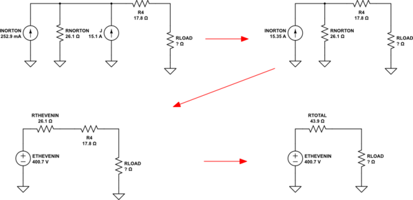
At this point, it's convenient to Nortonize the Thevenin source presented by \$E\$ and \$R_1+R_2\$ and then follow through with some steps, as shown below:
schematic

simulate this circuit

At this point, you should already know that the maximum power into \$R_\text{LOAD}\$ will occur when \$R_\text{LOAD}=R_\text{TOTAL}\$. (If not, you can compute this by developing a power equation and then solving for the derivative, where the slope is zero.)

The voltage at the load resistor will be exactly \$\frac12\$ of the applied voltage shown above. Given that you know that \$R_\text{LOAD}=R_\text{TOTAL}\$, you should now be able to easily work out the power in \$R_\text{LOAD}\$.


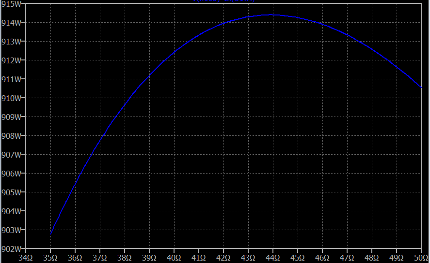
Here's a curve generated using Spice and your entire circuit (not some simplified form of it) to show the power in \$R_\text{LOAD}\$ as it's resistance is varied. You should expect to see something akin to a parabolic curve. And you do:

enter image description here

You can also see that the estimated resistance I'd calculated is consistent with the graph.

The left schematic combines \$R_1\$ and \$R_2\$. The right schematic eliminates \$R_3\$ since it has no impact on the current source (which has infinite impedance.)

schematic

simulate this circuit – Schematic created using CircuitLab

At this point, it's convenient to Nortonize the Thevenin source presented by \$E\$ and \$R_1+R_2\$ and then follow through with some steps, as shown below:

schematic

simulate this circuit

At this point, you should already know that the maximum power into \$R_\text{LOAD}\$ will occur when \$R_\text{LOAD}=R_\text{TOTAL}\$. (If not, you can compute this by developing a power equation and then solving for the derivative, where the slope is zero.)

The voltage at the load resistor will be exactly \$\frac12\$ of the applied voltage shown above. Given that you know that \$R_\text{LOAD}=R_\text{TOTAL}\$, you should now be able to easily work out the power in \$R_\text{LOAD}\$.


Here's a curve generated using Spice to show the power in \$R_\text{LOAD}\$ as it's resistance is varied. You should expect to see something akin to a parabolic curve. And you do:

enter image description here

You can also see that the estimated resistance I'd calculated is consistent with the graph.
The left schematic combines \$R_1\$ and \$R_2\$. The right schematic eliminates \$R_3\$ since it has no impact on the current source (which has infinite impedance.)

schematic

simulate this circuit – Schematic created using CircuitLab

At this point, it's convenient to Nortonize the Thevenin source presented by \$E\$ and \$R_1+R_2\$ and then follow through with some steps, as shown below:

schematic

simulate this circuit

At this point, you should already know that the maximum power into \$R_\text{LOAD}\$ will occur when \$R_\text{LOAD}=R_\text{TOTAL}\$. (If not, you can compute this by developing a power equation and then solving for the derivative, where the slope is zero.)

The voltage at the load resistor will be exactly \$\frac12\$ of the applied voltage shown above. Given that you know that \$R_\text{LOAD}=R_\text{TOTAL}\$, you should now be able to easily work out the power in \$R_\text{LOAD}\$.


Here's a curve generated using Spice and your entire circuit (not some simplified form of it) to show the power in \$R_\text{LOAD}\$ as it's resistance is varied. You should expect to see something akin to a parabolic curve. And you do:

enter image description here

You can also see that the estimated resistance I'd calculated is consistent with the graph.

added 367 characters in body
Source Link
jonk
  • 78.8k
  • 6
  • 81
  • 195

The left schematic combines \$R_1\$ and \$R_2\$. The right schematic eliminates \$R_3\$ since it has no impact on the current source (which has infinite impedance.)

schematic

simulate this circuit – Schematic created using CircuitLab

At this point, it's convenient to Nortonize the Thevenin source presented by \$E\$ and \$R_1+R_2\$ and then follow through with some steps, as shown below:

schematic

simulate this circuit

At this point, you should already know that the maximum power into \$R_\text{LOAD}\$ will occur when \$R_\text{LOAD}=R_\text{TOTAL}\$. (If not, you can compute this by developing a power equation and then solving for the derivative, where the slope is zero.)

The voltage at the load resistor will be exactly \$\frac12\$ of the applied voltage shown above. Given that you know that \$R_\text{LOAD}=R_\text{TOTAL}\$, you should now be able to easily work out the power in \$R_\text{LOAD}\$.


Here's a curve generated using Spice to show the power in \$R_\text{LOAD}\$ as it's resistance is varied. You should expect to see something akin to a parabolic curve. And you do:

enter image description here

You can also see that the estimated resistance I'd calculated is consistent with the graph.

The left schematic combines \$R_1\$ and \$R_2\$. The right schematic eliminates \$R_3\$ since it has no impact on the current source (which has infinite impedance.)

schematic

simulate this circuit – Schematic created using CircuitLab

At this point, it's convenient to Nortonize the Thevenin source presented by \$E\$ and \$R_1+R_2\$ and then follow through with some steps, as shown below:

schematic

simulate this circuit

At this point, you should already know that the maximum power into \$R_\text{LOAD}\$ will occur when \$R_\text{LOAD}=R_\text{TOTAL}\$. (If not, you can compute this by developing a power equation and then solving for the derivative, where the slope is zero.)

The voltage at the load resistor will be exactly \$\frac12\$ of the applied voltage shown above. Given that you know that \$R_\text{LOAD}=R_\text{TOTAL}\$, you should now be able to easily work out the power in \$R_\text{LOAD}\$.


Here's a curve generated using Spice to show the power in \$R_\text{LOAD}\$ as it's resistance is varied. You should expect to see something akin to a parabolic curve. And you do:

enter image description here

You can also see that the estimated resistance I'd calculated is consistent with the graph.

Source Link
jonk
  • 78.8k
  • 6
  • 81
  • 195

The left schematic combines \$R_1\$ and \$R_2\$. The right schematic eliminates \$R_3\$ since it has no impact on the current source (which has infinite impedance.)

schematic

simulate this circuit – Schematic created using CircuitLab

At this point, it's convenient to Nortonize the Thevenin source presented by \$E\$ and \$R_1+R_2\$ and then follow through with some steps, as shown below:

schematic

simulate this circuit

At this point, you should already know that the maximum power into \$R_\text{LOAD}\$ will occur when \$R_\text{LOAD}=R_\text{TOTAL}\$. (If not, you can compute this by developing a power equation and then solving for the derivative, where the slope is zero.)

The voltage at the load resistor will be exactly \$\frac12\$ of the applied voltage shown above. Given that you know that \$R_\text{LOAD}=R_\text{TOTAL}\$, you should now be able to easily work out the power in \$R_\text{LOAD}\$.