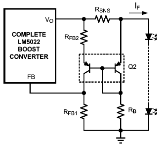
I came across this circuit for a high-side current sense using BJT current mirror, and I am trying to derive a formula for how I could calculate the sense voltage output (going to the FB pin) in terms of Isense and the resistors used. I am having a hard time understanding how they derived their formulas. Firstly where does the 1.25 come from to calculate their RFB1\$R_\mathrm{FB1}\$, and when it says suggested bias current of 1mA, is this talking about base current, and why 1mA?
Resistor RB\$R_\mathrm{B}\$ sets a bias current through the right-hand transistor. The suggested bias current for the PNP transistors is 1 mA. RB\$R_\mathrm{B}\$ is selected by dividing the typical output voltage minus one diode drop by 1 mA. RB = (VO – 0.6) / 0.001 = 32.6 kΩ (5)$$ R_\mathrm{B} = \frac{V_\mathrm{O} – 0.6}{0.001} = 32.6\mathrm{k}\Omega\label{1}\tag{5} $$ RB = 32.4 kΩ 1% (6)$$ R_\mathrm{B} = 32.4\mathrm{k}\Omega\pm 1\% \label{2}\tag{6} $$ RFB1\$R_\mathrm{FB1}\$ is set to bias the left-hand PNP at 1 mA, using the following expression. RFB1 = 1.25 / 0.001 = 1.25 kΩ (7)$$ R_\mathrm{FB1} = {1.25 \over 0.001} = 1.25\mathrm{k}\Omega \label{3}\tag{7} $$ RFB1 = 1.24 kΩ 1% (8)$$ R_\mathrm{FB1} = 1.24 \mathrm{k}\Omega\pm 1\% \label{4}\tag{8} $$ RFB2\$R_\mathrm{FB2}\$ is set to amplify the current sense signal to equal the feedback voltage: RFB2 = (IF x RSNS x RFB1) / 1.25 (9)$$ R_\mathrm{FB2} = \frac{I_\mathrm{F} \times R_\mathrm{SNS} \times R_\mathrm{FB1}}{1.25} \label{5}\tag{9} $$ RFB2 = (1.0 x 0.2 x 1240) / 1.25 = 198Ω (10)$$ R_\mathrm{FB2} = \frac{1.0 \times 0.2 \times 1240}{1.25} = 198\Omega \label{6}\tag{10} $$ RFB2 is 200Ω 1% (11)$$ R_\mathrm{FB2}\text{ is }200\Omega\pm 1\% \label{7}\tag{11} $$ Texas Instruments Application Note: AN-1696
Texas Instruments Application Note: AN-1696
Now using "1" for left transistor and "2" for right transistor:
From my understanding the base of the two transistors will be at VO - Vbe2\$V_\mathrm{O} - V_\mathrm{BE2}\$ (forward drop of right-hand transistor). Doing KVL around the top loop, you Have (RsenseIsense) + Vbe2 = Vbe1 + (RFB2Ie1). Forhave $$ R_\mathrm{SNS}\cdot I_\mathrm{SNS} + V_{BE2} = V_{BE1} + R_\mathrm{FB2}\cdot I_{E1}. $$ For a matched pair, where Vbe1 ~ Vbe2\$V_\mathrm{BE1} \sim V_\mathrm{BE2}\$, this gives: $$ R_\mathrm{SNS}\cdot I_\mathrm{SNS} = R_\mathrm{FB2}\cdot I_{E1}, $$ so (RsenseIsense) = (RFB2Ie1), so RFB2\$R_\mathrm{FB2}\$ has the same potential across it as Rsense\$R_\mathrm{SNS}\$, and for a given sense resistor and load current, Ie1\$I_\mathrm{E1}\$ is set by RFB2\$R_\mathrm{FB2}\$ as: Ie1 = (Rsense*Isense) $$ I_\mathrm{E1} = \frac{R_\mathrm{SNS}\cdot I_\mathrm{SNS}}{R_\mathrm{FB2}}. $$ Since / RFB2.
Since Ie1 >> Ib1\$I_\mathrm{E1} \gg I_\mathrm{B1}\$, then Ic1 ~ Ie1\$I_\mathrm{C1} \sim I_\mathrm{E1}\$, so Vsense ~ Ie1RFB1. so: Vsense = (RsenseIsense)*(RFB1 / RFB2)\$V_\mathrm{SNS}\sim I_\mathrm{E1}\cdot R_\mathrm{FB2}\$. So: $$ V_\mathrm{SNS} = R_\mathrm{SNS}\cdot I_\mathrm{SNS}\cdot\frac{R_\mathrm{FB1}}{R_\mathrm{FB2}}. $$
So is this a correct formula to use for the Vsense\$V_\mathrm{SNS}\$ output?
I think I'm not understanding something correctly, because I don't get what effect RB\$R_\mathrm{B}\$ actually has on this formula? The formula I derived above does not include RB\$R_\mathrm{B}\$, but I think the base current of both transistors is set by RB\$R_\mathrm{B}\$, and the collector/emitter current should be related to base current as an approximation: Ib = Ie $$ I_\mathrm{B} = \frac{I_\mathrm{E}}{\beta}, $$ where / Beta, Where Beta\$\beta\$ is the current gain - but if I try to derive a formula that way I can't seem to get the same result.
So where should base current and Beta\$\beta\$ come into these calculations?
Could you not just replace the transistor pair (emitter diodes) with two regular diodes OR'd together and connected to RFB1\$R_\mathrm{FB1}\$, and arrive at the same formula, and functionality?

