Corrected flowchart.
Source Link
Transistor
  • 180.3k
  • 14
  • 193
  • 417

Use modulo arithmetic.

// Pseudo-code
// error
error = (setPoint + 512 - currPos) % 1024 - 512;

This code shifts the setpoint from {0 .. 1023} to {512 .. 1535}, subtracts the actual position and gets the modulus. The answer will be in the range 0 - 1023 but will have a positive offset of 512 which is subtracted out. The resultant error will be in the range {-512 .. 511}.

Suppose my current position is 10 and setpoint is 1023. The error is 1023 - 10 = 1013 ...

error = (setPoint + 512 - currPos) % 1024 - 512;
// Calculation
error = (1023 + 512 - 10) % 1024 - 512
      = 1525 % 1024 - 512
      = 501 - 512
      = -11

Update 1.

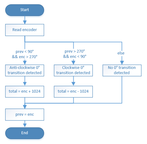
It seems that you want the geared output to run from 0° to 360° but that the assembly could overshoot slightly at 360° and, I presume, at 0°. The only way to handle this with your proportional control is to convert your encoder in software into a multi-turn encoder. This means keeping track of your revolutions and allowing your "total" value to run from, say, -90° to +450°.

enter image description hereenter image description here

Figure 1. Flowchart for 0° transition testing.

Use modulo arithmetic.

// Pseudo-code
// error
error = (setPoint + 512 - currPos) % 1024 - 512;

This code shifts the setpoint from {0 .. 1023} to {512 .. 1535}, subtracts the actual position and gets the modulus. The answer will be in the range 0 - 1023 but will have a positive offset of 512 which is subtracted out. The resultant error will be in the range {-512 .. 511}.

Suppose my current position is 10 and setpoint is 1023. The error is 1023 - 10 = 1013 ...

error = (setPoint + 512 - currPos) % 1024 - 512;
// Calculation
error = (1023 + 512 - 10) % 1024 - 512
      = 1525 % 1024 - 512
      = 501 - 512
      = -11

Update 1.

It seems that you want the geared output to run from 0° to 360° but that the assembly could overshoot slightly at 360° and, I presume, at 0°. The only way to handle this with your proportional control is to convert your encoder in software into a multi-turn encoder. This means keeping track of your revolutions and allowing your "total" value to run from, say, -90° to +450°.

enter image description here

Figure 1. Flowchart for 0° transition testing.
Use modulo arithmetic.

// Pseudo-code
// error
error = (setPoint + 512 - currPos) % 1024 - 512;

This code shifts the setpoint from {0 .. 1023} to {512 .. 1535}, subtracts the actual position and gets the modulus. The answer will be in the range 0 - 1023 but will have a positive offset of 512 which is subtracted out. The resultant error will be in the range {-512 .. 511}.

Suppose my current position is 10 and setpoint is 1023. The error is 1023 - 10 = 1013 ...

error = (setPoint + 512 - currPos) % 1024 - 512;
// Calculation
error = (1023 + 512 - 10) % 1024 - 512
      = 1525 % 1024 - 512
      = 501 - 512
      = -11

Update 1.

It seems that you want the geared output to run from 0° to 360° but that the assembly could overshoot slightly at 360° and, I presume, at 0°. The only way to handle this with your proportional control is to convert your encoder in software into a multi-turn encoder. This means keeping track of your revolutions and allowing your "total" value to run from, say, -90° to +450°.

enter image description here

Figure 1. Flowchart for 0° transition testing.
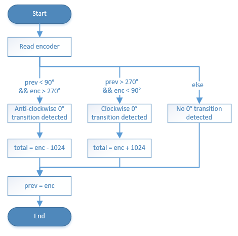
Added Figure 1, etc.
Source Link
Transistor
  • 180.3k
  • 14
  • 193
  • 417

Use modulo arithmetic.

// Pseudo-code
// error
error = (setPoint + 512 - currPos) % 1024 - 512;

This code shifts the setpoint from {0 .. 1023} to {512 .. 1535}, subtracts the actual position and gets the modulus. The answer will be in the range 0 - 1023 but will have a positive offset of 512 which is subtracted out. The resultant error will be in the range {-512 .. 511}.

Suppose my current position is 10 and setpoint is 1023. The error is 1023 - 10 = 1013 ...

error = (setPoint + 512 - currPos) % 1024 - 512;
// Calculation
error = (1023 + 512 - 10) % 1024 - 512
      = 1525 % 1024 - 512
      = 501 - 512
      = -11

Update 1.

It seems that you want the geared output to run from 0° to 360° but that the assembly could overshoot slightly at 360° and, I presume, at 0°. The only way to handle this with your proportional control is to convert your encoder in software into a multi-turn encoder. This means keeping track of your revolutions and allowing your "total" value to run from, say, -90° to +450°.

// Pseudo-code
// Angle       0                            360
//         ----+-----------------------------+-----
// O-flow -1   0    0    0    0    0    0    1    1

error = (setPoint + 512 - currPos) % 1024 - 512;

enter image description here

More later ...Figure 1. Flowchart for 0° transition testing.

Use modulo arithmetic.

// Pseudo-code
// error
error = (setPoint + 512 - currPos) % 1024 - 512;

This code shifts the setpoint from {0 .. 1023} to {512 .. 1535}, subtracts the actual position and gets the modulus. The answer will be in the range 0 - 1023 but will have a positive offset of 512 which is subtracted out. The resultant error will be in the range {-512 .. 511}.

Suppose my current position is 10 and setpoint is 1023. The error is 1023 - 10 = 1013 ...

error = (setPoint + 512 - currPos) % 1024 - 512;
// Calculation
error = (1023 + 512 - 10) % 1024 - 512
      = 1525 % 1024 - 512
      = 501 - 512
      = -11

Update 1.

It seems that you want the geared output to run from 0° to 360° but that the assembly could overshoot slightly at 360° and, I presume, at 0°. The only way to handle this with your proportional control is to convert your encoder in software into a multi-turn encoder.

// Pseudo-code
// Angle       0                            360
//         ----+-----------------------------+-----
// O-flow -1   0    0    0    0    0    0    1    1

error = (setPoint + 512 - currPos) % 1024 - 512;

More later ...

Use modulo arithmetic.

// Pseudo-code
// error
error = (setPoint + 512 - currPos) % 1024 - 512;

This code shifts the setpoint from {0 .. 1023} to {512 .. 1535}, subtracts the actual position and gets the modulus. The answer will be in the range 0 - 1023 but will have a positive offset of 512 which is subtracted out. The resultant error will be in the range {-512 .. 511}.

Suppose my current position is 10 and setpoint is 1023. The error is 1023 - 10 = 1013 ...

error = (setPoint + 512 - currPos) % 1024 - 512;
// Calculation
error = (1023 + 512 - 10) % 1024 - 512
      = 1525 % 1024 - 512
      = 501 - 512
      = -11

Update 1.

It seems that you want the geared output to run from 0° to 360° but that the assembly could overshoot slightly at 360° and, I presume, at 0°. The only way to handle this with your proportional control is to convert your encoder in software into a multi-turn encoder. This means keeping track of your revolutions and allowing your "total" value to run from, say, -90° to +450°.

enter image description here

Figure 1. Flowchart for 0° transition testing.

Response to comment.
Source Link
Transistor
  • 180.3k
  • 14
  • 193
  • 417

Use modulo arithmetic.

// Pseudo-code
// error
error = (setPoint + 512 - currPos) % 1024 - 512;

This code shifts the setpoint from {0 .. 1023} to {512 .. 1535}, subtracts the actual position and gets the modulus. The answer will be in the range 0 - 1023 but will have a positive offset of 512 which is subtracted out. The resultant error will be in the range {-512 .. 511}.

Suppose my current position is 10 and setpoint is 1023. The error is 1023 - 10 = 1013 ...

error = (setPoint + 512 - currPos) % 1024 - 512;
// Calculation
error = (1023 + 512 - 10) % 1024 - 512
      = 1525 % 1024 - 512
      = 501 - 512
      = -11

Update 1.

It seems that you want the geared output to run from 0° to 360° but that the assembly could overshoot slightly at 360° and, I presume, at 0°. The only way to handle this with your proportional control is to convert your encoder in software into a multi-turn encoder.

// Pseudo-code
// Angle       0                            360
//         ----+-----------------------------+-----
// O-flow -1   0    0    0    0    0    0    1    1

error = (setPoint + 512 - currPos) % 1024 - 512;

More later ...

Use modulo arithmetic.

// Pseudo-code
// error
error = (setPoint + 512 - currPos) % 1024 - 512;

This code shifts the setpoint from {0 .. 1023} to {512 .. 1535}, subtracts the actual position and gets the modulus. The answer will be in the range 0 - 1023 but will have a positive offset of 512 which is subtracted out. The resultant error will be in the range {-512 .. 511}.

Suppose my current position is 10 and setpoint is 1023. The error is 1023 - 10 = 1013 ...

error = (setPoint + 512 - currPos) % 1024 - 512;
// Calculation
error = (1023 + 512 - 10) % 1024 - 512
      = 1525 % 1024 - 512
      = 501 - 512
      = -11

Update 1.

It seems that you want the geared output to run from 0° to 360° but that the assembly could overshoot slightly at 360° and, I presume, at 0°. The only way to handle this with your proportional control is to convert your encoder in software into a multi-turn encoder.

// Pseudo-code
// Angle       0                            360
//         ----+-----------------------------+-----
// O-flow -1   0    0    0    0    0    0    1    1

error = (setPoint + 512 - currPos) % 1024 - 512;

More later ...

added 39 characters in body
Source Link
Transistor
  • 180.3k
  • 14
  • 193
  • 417
Loading
Post Undeleted by Transistor
added 39 characters in body
Source Link
Transistor
  • 180.3k
  • 14
  • 193
  • 417
Loading
Post Deleted by Transistor
Source Link
Transistor
  • 180.3k
  • 14
  • 193
  • 417
Loading