added PIC10F200 asm code.
Source Link
glen_geek
  • 27.6k
  • 1
  • 25
  • 56
;Drive an infra-red LED cathode with digital output pin GP2.
;LED anode goes to +5V thru small series resistor, at 38000 Hz.
;23 cycles of 38 kHz, lasting about 600 microseconds
;turn IRLED off (high), lasting about 900 microseconds.
;Repeat this sequence forever.
;Default internal clock speed is 4MHz: instruction rate is 1000000/sec.
;All timing depends on 1MHz instruction rate!
;DON'T FORGET TO PULL notMCLR to LOGIC HIGH, else nothing runs!! Don't let it float.
;If you pull notMCLR low, IRLED goes off, until notMCLR goes high again.
;Watchdog timer is active - code resets it.
;By default, internal comparator is disabled from interfering with GP2 output pin.
;December2018
;
#include p10f200.inc        ;register names defined here
;Macros:
#define ledon bcf GPIO,GP2  ;turn IRLED on by dragging cathode low.
#define ledoff bsf GPIO,GP2 ;turn IRLED off by dragging cathode high.

 __CONFIG _MCLRE_ON         ;GP3/MCLR pin functions as MCLR input..pull it high with
                            ;a resistor to light up LED. Pull it low to turn LED off.

cnt         equ 0x10        ;first available RAM location
burstcnt    equ 0x11        ;a counter for burst length
;---------------------------------------------------------------
;
    ORG 0000h           ;start address from power-up or watchdog
    andlw 0xFE          ;reset to zero least sig bit: disable FOSC/4 output on GP2
    movwf OSCCAL        ;write oscillator calibration byte.
    b   setup           ;go configure this simple environment...
;   
setup:
    movlw 0xDF          ;make GP2 available as programable I/O pin rather
    OPTION              ;than TMR0 clk...write it to OPTION register
mainloop:
    movlw 0x0b          ;make GPIO 2 an output (not input) for driving IRLED
    tris GPIO
    movlw .23           ; init counter for six-hundred microsecond loop timer
    movwf burstcnt      ;it will be decremented to zero later.

shloop:
    ledon               ;macro to turn on IRLED
    movlw 3             ;now waste some time....about 13us.
    movwf cnt
    decfsz cnt,f        ;a short time-wasting loop
    b $-1               ;loop for LED off period.
    clrwdt              ;clear the watchdog so it doesn't disturb us.

    ledoff              ;macro to turn off IRLED
    movlw 3             ;now waste some time....about 13us.
    movwf cnt
    decfsz cnt,f
    b $-1               ;time-wasting loop for LED on.
    decfsz burstcnt,f   ;done with 600 us burst?
    b shloop            ;no, complete this burst with more 38 kHz. cycles
;--------------------------------------------------------
    
    ledoff                  ;turn IRLED off for remaining 900 microseconds
    movlw   .149            ;time-wasting counter for 900 us.
    movwf cnt               ;initialize off period count
nhloop:
    nop
    nop
    nop
    decfsz cnt,f
    b nhloop                ;countdown loop for LED off period.
    
    b mainloop              ;start again....600:on, 900:off loop forever
;--------------------------------------------------------
    END                     ;finish assembler code.
clarify IR_receiver_module with a box. more details of microcontroller IRLED driver.
Source Link
glen_geek
  • 27.6k
  • 1
  • 25
  • 56

I see a fatal flaw with the infra-red optical link.
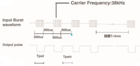
The infra-red receiver is expecting a "bursty" string of 38 kHz pulses. Data sheet explains that the 38 kHz should be on momentarily, about 600 microseconds, then off for 900 microseconds. The Chinese data sheet specifications are difficult to decipher:
ir receiver burst timing
When you transmit a continuous 38 kHz (as you are doing), the receiver becomes accustomed to the signal, just as your eyes become accustomed to the bright sun (and close down its iris). At least one user has noted that this receiver is also prone to sunlight-desensing. Other similar receivers might do better.

Your basic idea is sound, and that IR-receiver can work over the 1 M distance easily. Your 555 circuit driving the IRLED needs an additional timer to "break" for 900 microseconds. And your
The IR-receiver should include some way of keeping active low during that 900 microsecond break. I have added a 0.22uF capacitor to accomplish this function, but have made an assumption that the internal pull-up resistor is 39k ohms. Many IR-receivers have about this much resistance - the Chinese data sheet may not specify this part. The R1*C1 time constant is critical to bridge the needed 900 microsecond break:
improved LED driver to remove 900 us. burst I would use a very small microcontroller instead of 555 timer to drive the IRLED...fewer parts. It can generate the 38kHz burst lasting 600 microseconds, and time out the 900 microsecond "off" period too. It might even be able to drive the IRLED directly through a small value resistor.

I see a fatal flaw with the infra-red optical link.
The infra-red receiver is expecting a "bursty" string of 38 kHz pulses. Data sheet explains that the 38 kHz should be on momentarily, about 600 microseconds, then off for 900 microseconds. The Chinese data sheet specifications are difficult to decipher:
ir receiver burst timing
When you transmit a continuous 38 kHz (as you are doing), the receiver becomes accustomed to the signal, just as your eyes become accustomed to the bright sun (and close down its iris). At least one user has noted that this receiver is also prone to sunlight-desensing. Other similar receivers might do better.

Your basic idea is sound, and that IR-receiver can work over the 1 M distance easily. Your 555 circuit driving the IRLED needs an additional timer to "break" for 900 microseconds. And your IR-receiver should include some way of keeping active low during that 900 microsecond break:
improved LED driver to remove 900 us. burst I would use a very small microcontroller instead of 555 timer to drive the IRLED...fewer parts.

I see a fatal flaw with the infra-red optical link.
The infra-red receiver is expecting a "bursty" string of 38 kHz pulses. Data sheet explains that the 38 kHz should be on momentarily, about 600 microseconds, then off for 900 microseconds. The Chinese data sheet specifications are difficult to decipher:
ir receiver burst timing
When you transmit a continuous 38 kHz (as you are doing), the receiver becomes accustomed to the signal, just as your eyes become accustomed to the bright sun (and close down its iris). At least one user has noted that this receiver is also prone to sunlight-desensing. Other similar receivers might do better.

Your basic idea is sound, and that IR-receiver can work over the 1 M distance easily. Your 555 circuit driving the IRLED needs an additional timer to "break" for 900 microseconds.
The IR-receiver should include some way of keeping active low during that 900 microsecond break. I have added a 0.22uF capacitor to accomplish this function, but have made an assumption that the internal pull-up resistor is 39k ohms. Many IR-receivers have about this much resistance - the Chinese data sheet may not specify this part. The R1*C1 time constant is critical to bridge the needed 900 microsecond break:
improved LED driver to remove 900 us. burst I would use a very small microcontroller instead of 555 timer to drive the IRLED...fewer parts. It can generate the 38kHz burst lasting 600 microseconds, and time out the 900 microsecond "off" period too. It might even be able to drive the IRLED directly through a small value resistor.

clarify IR_receiver_module with a box
Source Link
glen_geek
  • 27.6k
  • 1
  • 25
  • 56

I see a fatal flaw with the infra-red optical link.
The infra-red receiver is expecting a "bursty" string of 38 kHz pulses. Data sheet explains that the 38 kHz should be on momentarily, about 600 microseconds, then off for 900 microseconds. The Chinese data sheet specifications are difficult to decipher:
ir receiver burst timing
When you transmit a continuous 38 kHz (as you are doing), the receiver becomes accustomed to the signal, just as your eyes become accustomed to the bright sun (and close down its iris). At least one user has noted that this receiver is also prone to sunlight-desensing. Other similar receivers might do better.

Your basic idea is sound, and that IR-receiver can work over the 1 M distance easily. Your 555 circuit driving the IRLED needs an additional timer to "break" for 900 microseconds. And your IR-receiver should include some way of keeping active low during that 900 microsecond break:
possible circuit improvement to remove "break"improved LED driver to remove 900 us. burst I would use a very small microcontroller instead of 555 timer to drive the IRLED...fewer parts.

I see a fatal flaw with the infra-red optical link.
The infra-red receiver is expecting a "bursty" string of 38 kHz pulses. Data sheet explains that the 38 kHz should be on momentarily, about 600 microseconds, then off for 900 microseconds. The Chinese data sheet specifications are difficult to decipher:
ir receiver burst timing
When you transmit a continuous 38 kHz (as you are doing), the receiver becomes accustomed to the signal, just as your eyes become accustomed to the bright sun (and close down its iris). At least one user has noted that this receiver is also prone to sunlight-desensing. Other similar receivers might do better.

Your basic idea is sound, and that IR-receiver can work over the 1 M distance easily. Your 555 circuit driving the IRLED needs an additional timer to "break" for 900 microseconds. And your IR-receiver should include some way of keeping active low during that 900 microsecond break:
possible circuit improvement to remove "break" I would use a very small microcontroller instead of 555 timer to drive the IRLED...fewer parts.

I see a fatal flaw with the infra-red optical link.
The infra-red receiver is expecting a "bursty" string of 38 kHz pulses. Data sheet explains that the 38 kHz should be on momentarily, about 600 microseconds, then off for 900 microseconds. The Chinese data sheet specifications are difficult to decipher:
ir receiver burst timing
When you transmit a continuous 38 kHz (as you are doing), the receiver becomes accustomed to the signal, just as your eyes become accustomed to the bright sun (and close down its iris). At least one user has noted that this receiver is also prone to sunlight-desensing. Other similar receivers might do better.

Your basic idea is sound, and that IR-receiver can work over the 1 M distance easily. Your 555 circuit driving the IRLED needs an additional timer to "break" for 900 microseconds. And your IR-receiver should include some way of keeping active low during that 900 microsecond break:
improved LED driver to remove 900 us. burst I would use a very small microcontroller instead of 555 timer to drive the IRLED...fewer parts.

add improved circuit, caveat about sunlight desensing
Source Link
glen_geek
  • 27.6k
  • 1
  • 25
  • 56
Loading
Source Link
glen_geek
  • 27.6k
  • 1
  • 25
  • 56
Loading