Bumped by Community user
appended answer 411325 as supplemental
Source Link
Dave Tweed
  • 178.3k
  • 17
  • 242
  • 418

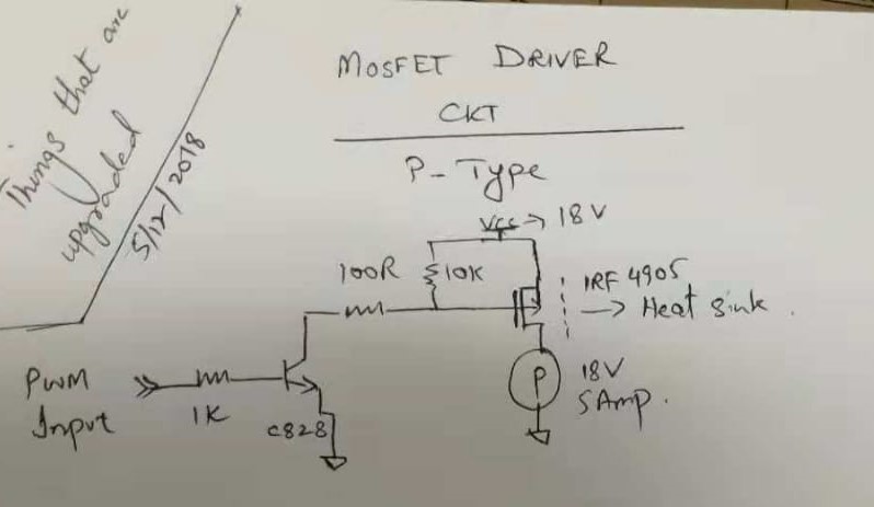
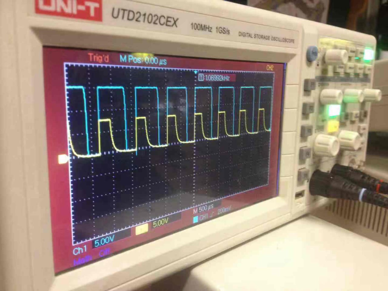
I am receiving PWM signal at 7.8V from a given controller, with which we need to control the speed of a DC motor at 18 V. I implemented the following circuit for this. enter image description here However, the output to motor signal (blue) is not following the original PWM (yellow) and duty cycle is increased by 50%. What could be the culprit. I dont think it is the awkward taper off on the downleg of the input signal enter image description here.
What could be a remedy?


How about this solution?

How to reduce MOSFET turn-off delay

I am receiving PWM signal at 7.8V from a given controller, with which we need to control the speed of a DC motor at 18 V. I implemented the following circuit for this. enter image description here However, the output to motor signal (blue) is not following the original PWM (yellow) and duty cycle is increased by 50%. What could be the culprit. I dont think it is the awkward taper off on the downleg of the input signal enter image description here.

What could be a remedy?


How about this solution?

How to reduce MOSFET turn-off delay

Source Link
Bilal
  • 31
  • 3

Mosfet Motor Drive amplifying duty cycle of PWM

I am receiving PWM signal at 7.8V from a given controller, with which we need to control the speed of a DC motor at 18 V. I implemented the following circuit for this. enter image description here However, the output to motor signal (blue) is not following the original PWM (yellow) and duty cycle is increased by 50%. What could be the culprit. I dont think it is the awkward taper off on the downleg of the input signal enter image description here.

What could be a remedy?