Set a couple of parameters first:
- Vz > VCC
- I(L) is steady state current
I(L) = VCC / Inductor_Resistance
The energy stored in the magnetic circuit is:
E(Joules) = 1/2 * L * I^2
This is the total energy dissipated in each on/off transition.
You need values for L, R, VCC, Vz and on/off repetition rate then you can calculate the time taken to discharge the energy stored in the inductor and the power dissipated in the Zener and the series R.
With the Zener you have instantaneous dissipation equal to (Vz - Vcc) * I(L) so the higher the value of Vz the faster you dissipate the energy in the inductor.
A really decent explanation is in this Maxim Appnote and ST Appnote. They describe using a Zener/FET combination, but the formula work for just a Zener too.
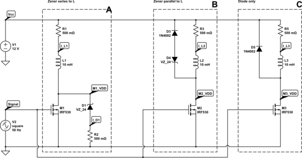
Update: It is interesting to see the impact on the time taken to dissipate the inductor stored energy. Below is the three common configurations:
- A diode across the inductor
- A zener plus a diode across the inductor (some use a TVS)
- A zener in series with the inductor

simulate this circuit – Schematic created using CircuitLab
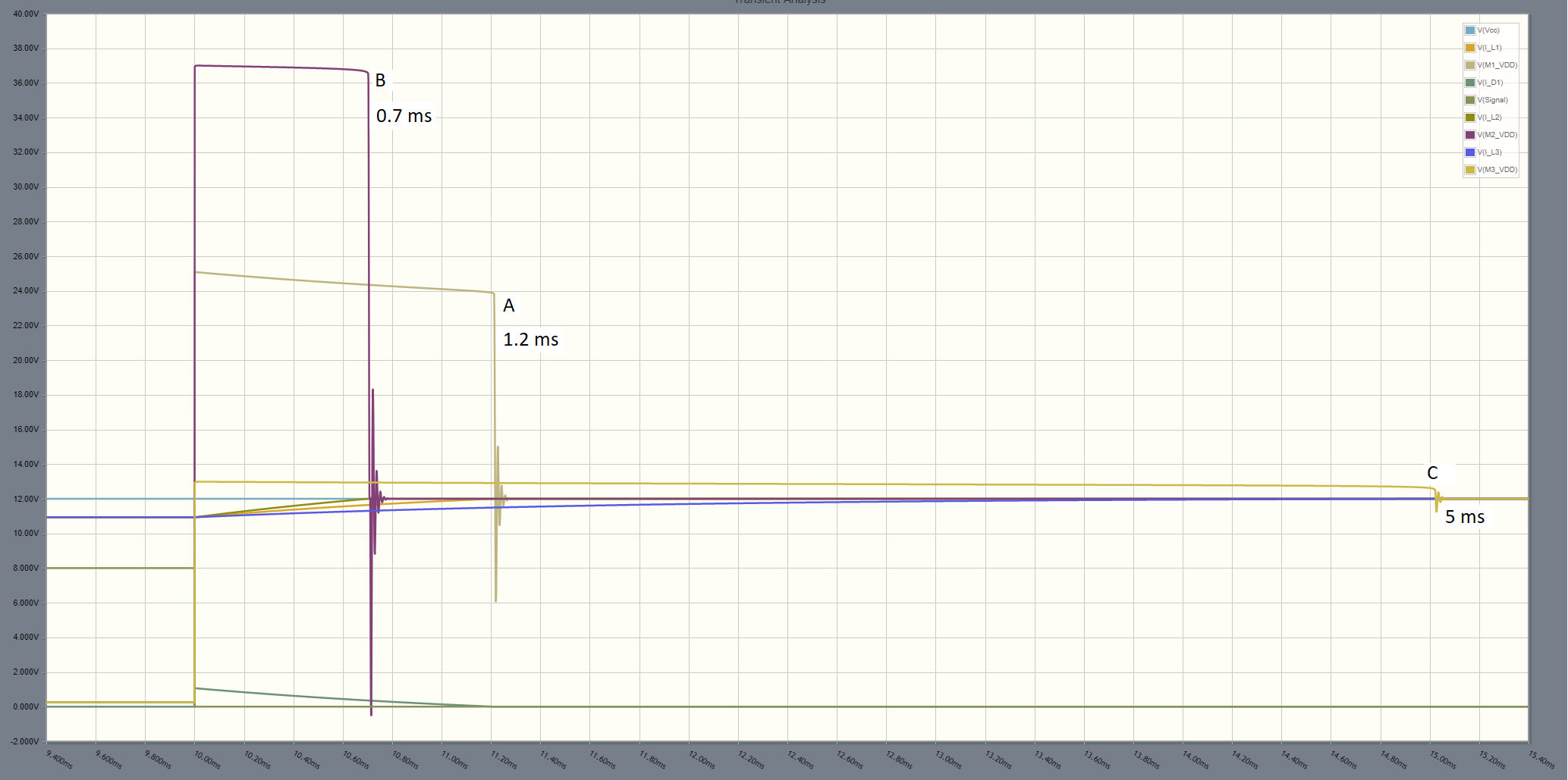
For the component values I used, the waveforms show that configuration B provides the shortest time to dissipate the energy in L, since it is ONLY dissipating the energy in L.
In configuration B the Zener dissipated twice the energy stored in L since it must dissipate an equal amount of energy from the power supply.
In configuration C the energy is mainly dissipated in the resistance associated with L so the time is approximately 5(LR).

