Bounty Ended with 50 reputation awarded by rrz0
OP has changed meaning of question.
Source Link
TimWescott
  • 47.1k
  • 1
  • 45
  • 108

This answer pertains to the question title "How to design an observer to estimate all states from a single sensor".

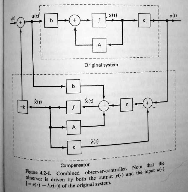
I'm pretty sure that you have the input vector to the compensator reversed. You either need to reverse the order that signals go into the multiplexer, or you need to reverse the order of the B matrix in the compensator (by changing it to [L B]. For reference here's a picture.

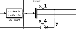
By picking off the \$x_1\$ term from your state vector you are also effectively using \$C=\left[\matrix{1 & 0 & 0 & 0}\right]\$. See the picture. I suspect, but do not know, that the tf2ss function returns C=[0 0 0 1], you should check this.

enter image description here

Note that Simulink will let you draw out the compensator pretty much the way it's done here -- it'll accept matrix gains and carry vector signals, and IIRC integrate vectors. So you can have a complete block diagram of what you want, instead of trying to get all the graphical 'i's and 't's dotted to match the textual specification in the definition block.

Figure 4.2-1 from Linear Systems

From Linear Systems, Kailath, Prentice-Hall, 1980.
This answer pertains to the question title "How to design an observer to estimate all states from a single sensor".

I'm pretty sure that you have the input vector to the compensator reversed. You either need to reverse the order that signals go into the multiplexer, or you need to reverse the order of the B matrix in the compensator (by changing it to [L B]. For reference here's a picture.

By picking off the \$x_1\$ term from your state vector you are also effectively using \$C=\left[\matrix{1 & 0 & 0 & 0}\right]\$. See the picture. I suspect, but do not know, that the tf2ss function returns C=[0 0 0 1], you should check this.

enter image description here

Note that Simulink will let you draw out the compensator pretty much the way it's done here -- it'll accept matrix gains and carry vector signals, and IIRC integrate vectors. So you can have a complete block diagram of what you want, instead of trying to get all the graphical 'i's and 't's dotted to match the textual specification in the definition block.

Figure 4.2-1 from Linear Systems

From Linear Systems, Kailath, Prentice-Hall, 1980.
added 342 characters in body
Source Link
TimWescott
  • 47.1k
  • 1
  • 45
  • 108

I'm pretty sure that you have the input vector to the compensator reversed. You either need to reverse the order that signals go into the multiplexer, or you need to reverse the order of the B matrix in the compensator (by changing it to [L B]. For reference here's a picture.

By picking off the \$x_1\$ term from your state vector you are also effectively using \$C=\left[\matrix{1 & 0 & 0 & 0}\right]\$. See the picture. I suspect, but do not know, that the tf2ss function returns C=[0 0 0 1], you should check this.

enter image description here

Note that Simulink will let you draw out the compensator pretty much the way it's done here -- it'll accept matrix gains and carry vector signals, and IIRC integrate vectors. So you can have a complete block diagram of what you want, instead of trying to get all the graphical 'i's and 't's dotted to match the textual specification in the definition block.

Figure 4.2-1 from Linear Systems

From Linear Systems, Kailath, Prentice-Hall, 1980.

I'm pretty sure that you have the input vector to the compensator reversed. You either need to reverse the order that signals go into the multiplexer, or you need to reverse the order of the B matrix in the compensator (by changing it to [L B]. For reference here's a picture.

By picking off the \$x_1\$ term from your state vector you are also effectively using \$C=\left[\matrix{1 & 0 & 0 & 0}\right]\$. See the picture. I suspect, but do not know, that the tf2ss function returns C=[0 0 0 1], you should check this.

enter image description here

Note that Simulink will let you draw out the compensator pretty much the way it's done here -- it'll accept matrix gains and carry vector signals, and IIRC integrate vectors. So you can have a complete block diagram of what you want, instead of trying to get all the graphical 'i's and 't's dotted to match the textual specification in the definition block.

Figure 4.2-1 from Linear Systems

From Linear Systems, Kailath, Prentice-Hall, 1980.

Source Link
TimWescott
  • 47.1k
  • 1
  • 45
  • 108

I'm pretty sure that you have the input vector to the compensator reversed. You either need to reverse the order that signals go into the multiplexer, or you need to reverse the order of the B matrix in the compensator (by changing it to [L B]. For reference here's a picture.

Note that Simulink will let you draw out the compensator pretty much the way it's done here -- it'll accept matrix gains and carry vector signals, and IIRC integrate vectors. So you can have a complete block diagram of what you want, instead of trying to get all the graphical 'i's and 't's dotted to match the textual specification in the definition block.

Figure 4.2-1 from Linear Systems

From Linear Systems, Kailath, Prentice-Hall, 1980.