Did update the link mentioning this is my book that I refer to.
Source Link
Verbal Kint
  • 23.5k
  • 1
  • 19
  • 57

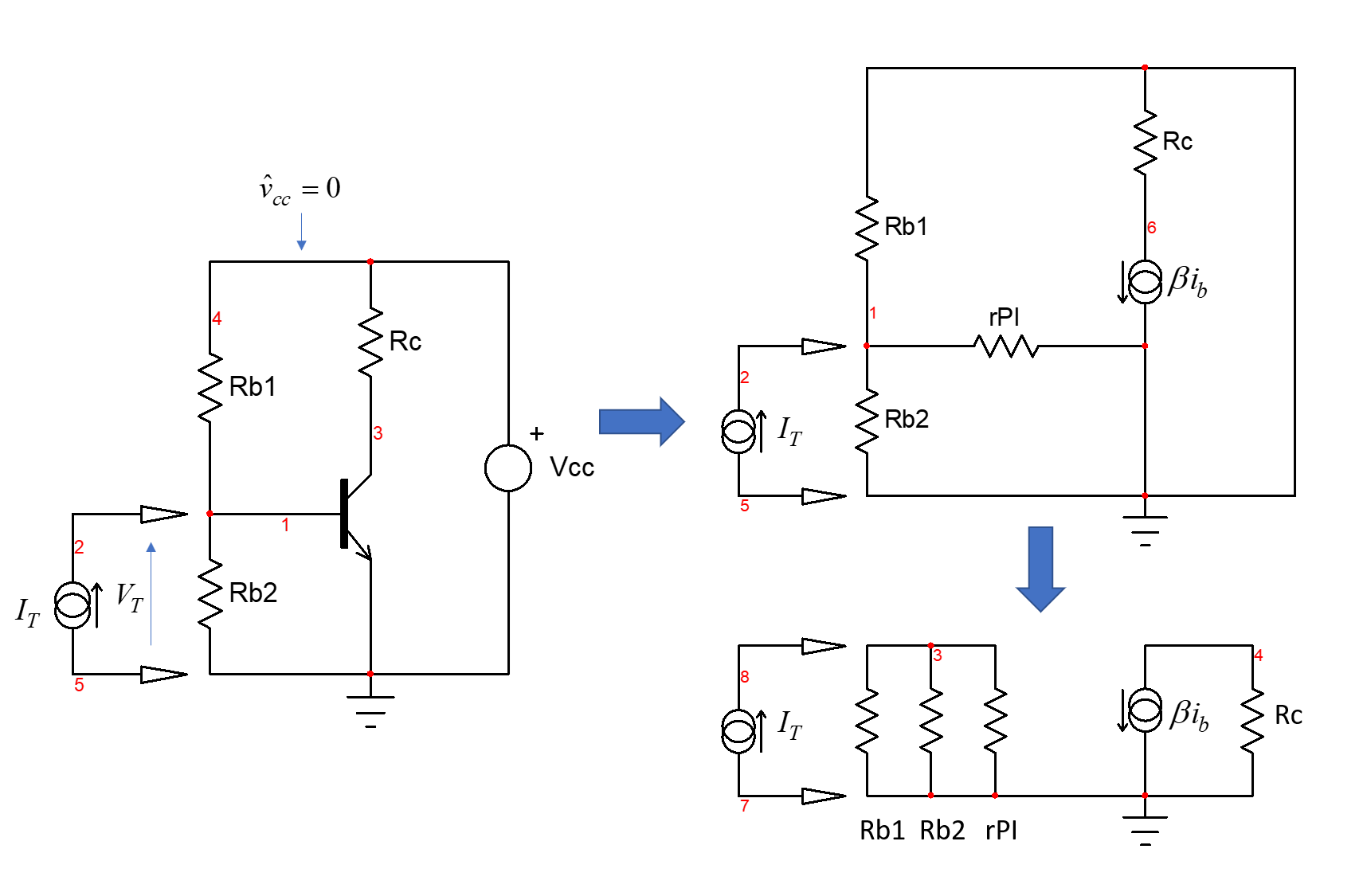
When you determine an input impedance (which is a transfer function), you install a test generator (the stimulus) \$I_T\$ across the connecting ports and you determine the response voltage \$V_T\$ collected across the current source terminals. This configuration is called a DPI or driving point impedance as described by the fast analytical circuits techniques or FACTs as described in my FACTsbook on the subject. The circuit below shows the configuration for the bipolar amplifier you described:

enter image description here

When you do that, you imply that the source supplying your circuit is uncorrelated with the stimulus. It means that if you sweep the input impedance with \$I_T\$, you won't see any ripple over the \$V_{cc}\$ rail supplied by a perfect dc source (0 output impedance). The small-signal amplitude of the \$V_{cc}\$ rail is thus 0 V during the analysis and the source can be replaced by a short circuit for the dynamic analysis. You can also imagine an infinite decoupling capacitor from the \$V_{cc}\$ rail to ground perfectly decoupling the rail during the analysis. As the drawing shows, when the source is shorted, the biasing resistances naturally come in parallel.

When you determine an input impedance (which is a transfer function), you install a test generator (the stimulus) \$I_T\$ across the connecting ports and you determine the response voltage \$V_T\$ collected across the current source terminals. This configuration is called a DPI or driving point impedance as described by the fast analytical circuits techniques or FACTs. The circuit below shows the configuration for the bipolar amplifier you described:

enter image description here

When you do that, you imply that the source supplying your circuit is uncorrelated with the stimulus. It means that if you sweep the input impedance with \$I_T\$, you won't see any ripple over the \$V_{cc}\$ rail supplied by a perfect dc source (0 output impedance). The small-signal amplitude of the \$V_{cc}\$ rail is thus 0 V during the analysis and the source can be replaced by a short circuit for the dynamic analysis. You can also imagine an infinite decoupling capacitor from the \$V_{cc}\$ rail to ground perfectly decoupling the rail during the analysis. As the drawing shows, when the source is shorted, the biasing resistances naturally come in parallel.

When you determine an input impedance (which is a transfer function), you install a test generator (the stimulus) \$I_T\$ across the connecting ports and you determine the response voltage \$V_T\$ collected across the current source terminals. This configuration is called a DPI or driving point impedance as described by the fast analytical circuits techniques or FACTs as described in my book on the subject. The circuit below shows the configuration for the bipolar amplifier you described:

enter image description here

When you do that, you imply that the source supplying your circuit is uncorrelated with the stimulus. It means that if you sweep the input impedance with \$I_T\$, you won't see any ripple over the \$V_{cc}\$ rail supplied by a perfect dc source (0 output impedance). The small-signal amplitude of the \$V_{cc}\$ rail is thus 0 V during the analysis and the source can be replaced by a short circuit for the dynamic analysis. You can also imagine an infinite decoupling capacitor from the \$V_{cc}\$ rail to ground perfectly decoupling the rail during the analysis. As the drawing shows, when the source is shorted, the biasing resistances naturally come in parallel.

Source Link
Verbal Kint
  • 23.5k
  • 1
  • 19
  • 57

When you determine an input impedance (which is a transfer function), you install a test generator (the stimulus) \$I_T\$ across the connecting ports and you determine the response voltage \$V_T\$ collected across the current source terminals. This configuration is called a DPI or driving point impedance as described by the fast analytical circuits techniques or FACTs. The circuit below shows the configuration for the bipolar amplifier you described:

enter image description here

When you do that, you imply that the source supplying your circuit is uncorrelated with the stimulus. It means that if you sweep the input impedance with \$I_T\$, you won't see any ripple over the \$V_{cc}\$ rail supplied by a perfect dc source (0 output impedance). The small-signal amplitude of the \$V_{cc}\$ rail is thus 0 V during the analysis and the source can be replaced by a short circuit for the dynamic analysis. You can also imagine an infinite decoupling capacitor from the \$V_{cc}\$ rail to ground perfectly decoupling the rail during the analysis. As the drawing shows, when the source is shorted, the biasing resistances naturally come in parallel.