added 2 characters in body
Source Link
WhatRoughBeast
  • 61k
  • 2
  • 38
  • 97

You have specified a superconducting shunt, with zero resistance. What you have not done is to specify its inductance. And you cannot force inductance to zero.

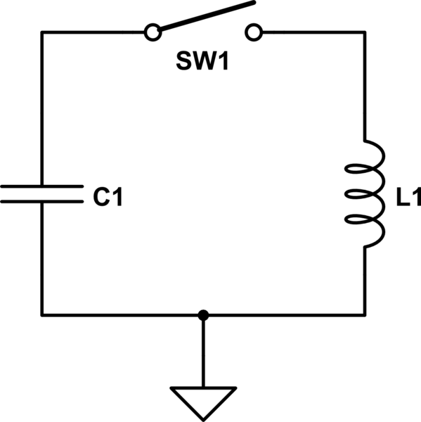
So your circuit looks like
schematic

simulate this circuit – Schematic created using CircuitLab

Let's say the cap is at some voltage V0. When you close the switch, the cap is at full voltage, and the current through the inductor is zero. As the current through the inductor rises, the voltage across the cap will fall. At some point the cap voltage will be zero, but the inductor current will be at maximum, and the capacitor voltage will be driven negative. As the capacitor voltage becomes more negative, the inductor current will drop, and when the cap is at -V0 the inductor current will be zero, and the process will start again in the other direction.

So the voltage and currents will both be sinusoidal, and phase shifted by 90 degrees wrt each other.

The maximum current can be determined by observing that the magnetic energy stored in the inductor at peak current equals the energy stored in the cap at peak voltage. If you know V0, C and L, you can calculate i(max). The frequency of the oscillations will be $$ f = \frac{1}{2\pi \sqrt{LC}}$$

Of course, in real life the magnetic field in the inductor will extend beyond the inductor, and any conductor within this changing magnetic field will have a voltage induced and will dissipate power. This means that the amplitude of both voltage and current will be gradually reduced, and eventually they will approach zero. At this point all of the energy stored in the cap will have been dissipated in the surrounding material. Plus, this interaction with the surroundings will alter the oscillation frequency.

EDIT - As Eliot Anderson has commented/implied, I did not actually answer the question as asked. Instead, I rejected the idea of an ideal shunt, and explained the issue in terms of what we laughingly call reality. So let me try to rectify the situation.

Assuming an ideal shunt, with neither resistance nor inductance, what happens to the charge? The simplest answer is that the question cannot be answered. When the switch is closed, the current becomes $$i=\frac{V}{R} $$ However, there is a really basic rule to follow (unless you get into more advanced mathematics): never divide by zero. This will always get you into bad territory. And for an ideal shunt the resistance is zero. So don't do it. Just don't.

There is another way to look at it which may help (and may not). If the shunt has a non-zero resistance, you can calculate how much powerenergy will be dissipated in discharging the cap, and not surprisingly it works out to the amount of energy in the cap when you started, and the result is the same for any non-zero value of R. So, if you want to look at things crosseyed, you can say that, since the powerenergy dissipated in the shunt remains constant regardless of the resistance, you can take the limit as the resistance approaches zero, and this will be the same constant value.

Ahem. Yes, there's a problem with this. The simple answer is that the value of the current and power cannot be computed, and the underlying assumptions made in taking the limit don't apply - so you can't take this particular limit.

Or maybe it's just simpler to say Thou Shalt Not Divide By Zero and be done with it.

You have specified a superconducting shunt, with zero resistance. What you have not done is to specify its inductance. And you cannot force inductance to zero.

So your circuit looks like

schematic

simulate this circuit – Schematic created using CircuitLab

Let's say the cap is at some voltage V0. When you close the switch, the cap is at full voltage, and the current through the inductor is zero. As the current through the inductor rises, the voltage across the cap will fall. At some point the cap voltage will be zero, but the inductor current will be at maximum, and the capacitor voltage will be driven negative. As the capacitor voltage becomes more negative, the inductor current will drop, and when the cap is at -V0 the inductor current will be zero, and the process will start again in the other direction.

So the voltage and currents will both be sinusoidal, and phase shifted by 90 degrees wrt each other.

The maximum current can be determined by observing that the magnetic energy stored in the inductor at peak current equals the energy stored in the cap at peak voltage. If you know V0, C and L, you can calculate i(max). The frequency of the oscillations will be $$ f = \frac{1}{2\pi \sqrt{LC}}$$

Of course, in real life the magnetic field in the inductor will extend beyond the inductor, and any conductor within this changing magnetic field will have a voltage induced and will dissipate power. This means that the amplitude of both voltage and current will be gradually reduced, and eventually they will approach zero. At this point all of the energy stored in the cap will have been dissipated in the surrounding material. Plus, this interaction with the surroundings will alter the oscillation frequency.

EDIT - As Eliot Anderson has commented/implied, I did not actually answer the question as asked. Instead, I rejected the idea of an ideal shunt, and explained the issue in terms of what we laughingly call reality. So let me try to rectify the situation.

Assuming an ideal shunt, with neither resistance nor inductance, what happens to the charge? The simplest answer is that the question cannot be answered. When the switch is closed, the current becomes $$i=\frac{V}{R} $$ However, there is a really basic rule to follow (unless you get into more advanced mathematics): never divide by zero. This will always get you into bad territory. And for an ideal shunt the resistance is zero. So don't do it. Just don't.

There is another way to look at it which may help (and may not). If the shunt has a non-zero resistance, you can calculate how much power will be dissipated in discharging the cap, and not surprisingly it works out to the amount of energy in the cap when you started, and the result is the same for any non-zero value of R. So, if you want to look at things crosseyed, you can say that, since the power dissipated in the shunt remains constant regardless of the resistance, you can take the limit as the resistance approaches zero, and this will be the same constant value.

Ahem. Yes, there's a problem with this. The simple answer is that the value of the current and power cannot be computed, and the underlying assumptions made in taking the limit don't apply - so you can't take this particular limit.

Or maybe it's just simpler to say Thou Shalt Not Divide By Zero and be done with it.

You have specified a superconducting shunt, with zero resistance. What you have not done is to specify its inductance. And you cannot force inductance to zero.

So your circuit looks like

schematic

simulate this circuit – Schematic created using CircuitLab

Let's say the cap is at some voltage V0. When you close the switch, the cap is at full voltage, and the current through the inductor is zero. As the current through the inductor rises, the voltage across the cap will fall. At some point the cap voltage will be zero, but the inductor current will be at maximum, and the capacitor voltage will be driven negative. As the capacitor voltage becomes more negative, the inductor current will drop, and when the cap is at -V0 the inductor current will be zero, and the process will start again in the other direction.

So the voltage and currents will both be sinusoidal, and phase shifted by 90 degrees wrt each other.

The maximum current can be determined by observing that the magnetic energy stored in the inductor at peak current equals the energy stored in the cap at peak voltage. If you know V0, C and L, you can calculate i(max). The frequency of the oscillations will be $$ f = \frac{1}{2\pi \sqrt{LC}}$$

Of course, in real life the magnetic field in the inductor will extend beyond the inductor, and any conductor within this changing magnetic field will have a voltage induced and will dissipate power. This means that the amplitude of both voltage and current will be gradually reduced, and eventually they will approach zero. At this point all of the energy stored in the cap will have been dissipated in the surrounding material. Plus, this interaction with the surroundings will alter the oscillation frequency.

EDIT - As Eliot Anderson has commented/implied, I did not actually answer the question as asked. Instead, I rejected the idea of an ideal shunt, and explained the issue in terms of what we laughingly call reality. So let me try to rectify the situation.

Assuming an ideal shunt, with neither resistance nor inductance, what happens to the charge? The simplest answer is that the question cannot be answered. When the switch is closed, the current becomes $$i=\frac{V}{R} $$ However, there is a really basic rule to follow (unless you get into more advanced mathematics): never divide by zero. This will always get you into bad territory. And for an ideal shunt the resistance is zero. So don't do it. Just don't.

There is another way to look at it which may help (and may not). If the shunt has a non-zero resistance, you can calculate how much energy will be dissipated in discharging the cap, and not surprisingly it works out to the amount of energy in the cap when you started, and the result is the same for any non-zero value of R. So, if you want to look at things crosseyed, you can say that, since the energy dissipated in the shunt remains constant regardless of the resistance, you can take the limit as the resistance approaches zero, and this will be the same constant value.

Ahem. Yes, there's a problem with this. The simple answer is that the value of the current and power cannot be computed, and the underlying assumptions made in taking the limit don't apply - so you can't take this particular limit.

Or maybe it's just simpler to say Thou Shalt Not Divide By Zero and be done with it.

added 1630 characters in body
Source Link
WhatRoughBeast
  • 61k
  • 2
  • 38
  • 97

You have specified a superconducting shunt, with zero resistance. What you have not done is to specify its inductance. And you cannot force inductance to zero.

So your circuit looks like

schematic

simulate this circuit – Schematic created using CircuitLab

Let's say the cap is at some voltage V0. When you close the switch, the cap is at full voltage, and the current through the inductor is zero. As the current through the inductor rises, the voltage across the cap will fall. At some point the cap voltage will be zero, but the inductor current will be at maximum, and the capacitor voltage will be driven negative. As the capacitor voltage becomes more negative, the inductor current will drop, and when the cap is at -V0 the inductor current will be zero, and the process will start again in the other direction.

So the voltage and currents will both be sinusoidal, and phase shifted by 90 degrees wrt each other.

The maximum current can be determined by observing that the magnetic energy stored in the inductor at peak current equals the energy stored in the cap at peak voltage. If you know V0, C and L, you can calculate i(max). The frequency of the oscillations will be $$ f = \frac{1}{2\pi \sqrt{LC}}$$

Of course, in real life the magnetic field in the inductor will extend beyond the inductor, and any conductor within this changing magnetic field will have a voltage induced and will dissipate power. This means that the amplitude of both voltage and current will be gradually reduced, and eventually they will approach zero. At this point all of the energy stored in the cap will have been dissipated in the surrounding material. Plus, this interaction with the surroundings will alter the oscillation frequency.

EDIT - As Eliot Anderson has commented/implied, I did not actually answer the question as asked. Instead, I rejected the idea of an ideal shunt, and explained the issue in terms of what we laughingly call reality. So let me try to rectify the situation.

Assuming an ideal shunt, with neither resistance nor inductance, what happens to the charge? The simplest answer is that the question cannot be answered. When the switch is closed, the current becomes $$i=\frac{V}{R} $$ However, there is a really basic rule to follow (unless you get into more advanced mathematics): never divide by zero. This will always get you into bad territory. And for an ideal shunt the resistance is zero. So don't do it. Just don't.

There is another way to look at it which may help (and may not). If the shunt has a non-zero resistance, you can calculate how much power will be dissipated in discharging the cap, and not surprisingly it works out to the amount of energy in the cap when you started, and the result is the same for any non-zero value of R. So, if you want to look at things crosseyed, you can say that, since the power dissipated in the shunt remains constant regardless of the resistance, you can take the limit as the resistance approaches zero, and this will be the same constant value.

Ahem. Yes, there's a problem with this. The simple answer is that the value of the current and power cannot be computed, and the underlying assumptions made in taking the limit don't apply - so you can't take this particular limit.

Or maybe it's just simpler to say Thou Shalt Not Divide By Zero and be done with it.

You have specified a superconducting shunt, with zero resistance. What you have not done is to specify its inductance. And you cannot force inductance to zero.

So your circuit looks like

schematic

simulate this circuit – Schematic created using CircuitLab

Let's say the cap is at some voltage V0. When you close the switch, the cap is at full voltage, and the current through the inductor is zero. As the current through the inductor rises, the voltage across the cap will fall. At some point the cap voltage will be zero, but the inductor current will be at maximum, and the capacitor voltage will be driven negative. As the capacitor voltage becomes more negative, the inductor current will drop, and when the cap is at -V0 the inductor current will be zero, and the process will start again in the other direction.

So the voltage and currents will both be sinusoidal, and phase shifted by 90 degrees wrt each other.

The maximum current can be determined by observing that the magnetic energy stored in the inductor at peak current equals the energy stored in the cap at peak voltage. If you know V0, C and L, you can calculate i(max). The frequency of the oscillations will be $$ f = \frac{1}{2\pi \sqrt{LC}}$$

Of course, in real life the magnetic field in the inductor will extend beyond the inductor, and any conductor within this changing magnetic field will have a voltage induced and will dissipate power. This means that the amplitude of both voltage and current will be gradually reduced, and eventually they will approach zero. At this point all of the energy stored in the cap will have been dissipated in the surrounding material. Plus, this interaction with the surroundings will alter the oscillation frequency.

EDIT - As Eliot Anderson has commented/implied, I did not actually answer the question as asked. Instead, I rejected the idea of an ideal shunt, and explained the issue in terms of what we laughingly call reality. So let me try to rectify the situation.

Assuming an ideal shunt, with neither resistance nor inductance, what happens to the charge? The simplest answer is that the question cannot be answered. When the switch is closed, the current becomes $$i=\frac{V}{R} $$ However, there is a really basic rule to follow (unless you get into more advanced mathematics): never divide by zero. This will always get you into bad territory. And for an ideal shunt the resistance is zero. So don't do it. Just don't.

There is another way to look at it which may help (and may not). If the shunt has a non-zero resistance, you can calculate how much power will be dissipated in discharging the cap, and not surprisingly it works out to the amount of energy in the cap when you started, and the result is the same for any non-zero value of R. So, if you want to look at things crosseyed, you can say that, since the power dissipated in the shunt remains constant regardless of the resistance, you can take the limit as the resistance approaches zero, and this will be the same constant value.

Ahem. Yes, there's a problem with this. The simple answer is that the value of the current and power cannot be computed, and the underlying assumptions made in taking the limit don't apply - so you can't take this particular limit.

Or maybe it's just simpler to say Thou Shalt Not Divide By Zero and be done with it.

Added emphasis to critical phrase
Source Link
Elliot Alderson
  • 31.7k
  • 5
  • 31
  • 68

You have specified a superconducting shunt, with zero resistance. What you have not done is to specify its inductance. And you cannot force inductance to zero.And you cannot force inductance to zero.

So your circuit looks like

schematic

simulate this circuit – Schematic created using CircuitLab

Let's say the cap is at some voltage V0. When you close the switch, the cap is at full voltage, and the current through the inductor is zero. As the current through the inductor rises, the voltage across the cap will fall. At some point the cap voltage will be zero, but the inductor current will be at maximum, and the capacitor voltage will be driven negative. As the capacitor voltage becomes more negative, the inductor current will drop, and when the cap is at -V0 the inductor current will be zero, and the process will start again in the other direction.

So the voltage and currents will both be sinusoidal, and phase shifted by 90 degrees wrt each other.

The maximum current can be determined by observing that the magnetic energy stored in the inductor at peak current equals the energy stored in the cap at peak voltage. If you know V0, C and L, you can calculate i(max). The frequency of the oscillations will be $$ f = \frac{1}{2\pi \sqrt{LC}}$$

Of course, in real life the magnetic field in the inductor will extend beyond the inductor, and any conductor within this changing magnetic field will have a voltage induced and will dissipate power. This means that the amplitude of both voltage and current will be gradually reduced, and eventually they will approach zero. At this point all of the energy stored in the cap will have been dissipated in the surrounding material. Plus, this interaction with the surroundings will alter the oscillation frequency.

You have specified a superconducting shunt, with zero resistance. What you have not done is to specify its inductance. And you cannot force inductance to zero.

So your circuit looks like

schematic

simulate this circuit – Schematic created using CircuitLab

Let's say the cap is at some voltage V0. When you close the switch, the cap is at full voltage, and the current through the inductor is zero. As the current through the inductor rises, the voltage across the cap will fall. At some point the cap voltage will be zero, but the inductor current will be at maximum, and the capacitor voltage will be driven negative. As the capacitor voltage becomes more negative, the inductor current will drop, and when the cap is at -V0 the inductor current will be zero, and the process will start again in the other direction.

So the voltage and currents will both be sinusoidal, and phase shifted by 90 degrees wrt each other.

The maximum current can be determined by observing that the magnetic energy stored in the inductor at peak current equals the energy stored in the cap at peak voltage. If you know V0, C and L, you can calculate i(max). The frequency of the oscillations will be $$ f = \frac{1}{2\pi \sqrt{LC}}$$

Of course, in real life the magnetic field in the inductor will extend beyond the inductor, and any conductor within this changing magnetic field will have a voltage induced and will dissipate power. This means that the amplitude of both voltage and current will be gradually reduced, and eventually they will approach zero. At this point all of the energy stored in the cap will have been dissipated in the surrounding material. Plus, this interaction with the surroundings will alter the oscillation frequency.

Source Link
WhatRoughBeast
  • 61k
  • 2
  • 38
  • 97
Loading