added 341 characters in body
Source Link
D.A.S.
  • 148.1k
  • 3
  • 56
  • 190

Droplets of Poly. will diffuse light easily and may be detected dropping past a vertical camera with a diffused back reflector such that the attenuation loss from the reflection coefficient and light spreading is easily detected with 1/60th second captures over a 1cm area or a droplet speed of 60 cm/s. If it is faster, then define it.

It is possible to locate an optical sensor 5x5mm10mm effective aperture camera array to accept a calibration drop and measure the offset from the optical datum home switch to measure any change from the working position home defined as the xy axis droplet centre position. This can be used to create a new home work position from which a stepper gantry can then locate to the system design accuracy be it full steps of say 0.5mm or 1/16 steps of < 0.05mm accuracy.

The g-codes for doing the correction calibration is easy. The challenge is to choose an optical reflective array sensor like a 9600 dpi laser mouse chip to detect the peak centre of the droplet and convert this into a geometric work 0,0 position which is just near the datum 0,0 optical home positions in a corner or single linear axis. Cleaning the array sensor after calibration might be a manual operation.

Here the SNR of the optical array signals only have to report the error in the geometric xy mean of the optical array. This can confirm as a go-no go or be used in error correction for position error in the servo by some method. TBD

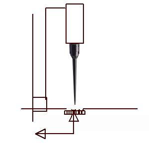
enter image description here

It is possible to locate an optical sensor 5x5mm array to accept a calibration drop and measure the offset from the optical datum home switch to measure any change from the working position home defined as the xy axis droplet centre position. This can be used to create a new home work position from which a stepper gantry can then locate to the system design accuracy be it full steps of say 0.5mm or 1/16 steps of < 0.05mm accuracy.

The g-codes for doing the correction calibration is easy. The challenge is to choose an optical reflective array sensor like a 9600 dpi laser mouse chip to detect the peak centre of the droplet and convert this into a geometric work 0,0 position which is just near the datum 0,0 optical home positions in a corner or single linear axis. Cleaning the array sensor after calibration might be a manual operation.

Here the SNR of the optical array signals only have to report the error in the geometric xy mean of the optical array. This can confirm as a go-no go or be used in error correction for position error in the servo by some method. TBD

enter image description here

Droplets of Poly. will diffuse light easily and may be detected dropping past a vertical camera with a diffused back reflector such that the attenuation loss from the reflection coefficient and light spreading is easily detected with 1/60th second captures over a 1cm area or a droplet speed of 60 cm/s. If it is faster, then define it.

It is possible to locate an optical sensor 10mm effective aperture camera array to accept a calibration drop and measure the offset from the optical datum home switch to measure any change from the working position home defined as the xy axis droplet centre position. This can be used to create a new home work position from which a stepper gantry can then locate to the system design accuracy be it full steps of say 0.5mm or 1/16 steps of < 0.05mm accuracy.

The g-codes for doing the correction calibration is easy. The challenge is to choose an optical reflective array sensor like a 9600 dpi laser mouse chip to detect the peak centre of the droplet and convert this into a geometric work 0,0 position which is just near the datum 0,0 optical home positions in a corner or single linear axis. Cleaning the array sensor after calibration might be a manual operation.

Here the SNR of the optical array signals only have to report the error in the geometric xy mean of the optical array. This can confirm as a go-no go or be used in error correction for position error in the servo by some method. TBD

enter image description here

Source Link
D.A.S.
  • 148.1k
  • 3
  • 56
  • 190

It is possible to locate an optical sensor 5x5mm array to accept a calibration drop and measure the offset from the optical datum home switch to measure any change from the working position home defined as the xy axis droplet centre position. This can be used to create a new home work position from which a stepper gantry can then locate to the system design accuracy be it full steps of say 0.5mm or 1/16 steps of < 0.05mm accuracy.

The g-codes for doing the correction calibration is easy. The challenge is to choose an optical reflective array sensor like a 9600 dpi laser mouse chip to detect the peak centre of the droplet and convert this into a geometric work 0,0 position which is just near the datum 0,0 optical home positions in a corner or single linear axis. Cleaning the array sensor after calibration might be a manual operation.

Here the SNR of the optical array signals only have to report the error in the geometric xy mean of the optical array. This can confirm as a go-no go or be used in error correction for position error in the servo by some method. TBD

enter image description here