Bumped by Community user
Tweeted twitter.com/StackElectronix/status/1108473384936067075
added 15 characters in body
Source Link
Steve
  • 1.1k
  • 9
  • 28

I have met with a scalar control algorithm for a permanent magnet synchronous motor. I haven´t heard about it before so I decided to develop a dynamic model to further analyze this control algorithm. Unfortunatelly I haven´t got the Matlab with the SimPowerSystems library so I decided to create this model in Scilab.

I have been using below given equations for PMSM simulation:

\$\frac{\mathrm{d}i_d}{\mathrm{d}t} = \frac{1}{L_d}(u_d-R\cdot i_q+L_q\cdot\omega_e\cdot i_q), \\ \frac{\mathrm{d}i_q}{\mathrm{d}t} = \frac{1}{L_q}(u_q-R\cdot i_q-L_d\cdot\omega_e\cdot i_d - \omega_e\cdot\psi_m), \\ \frac{\mathrm{d}\omega_m}{\mathrm{d}t} = \frac{1}{J}(1.5\cdot p\cdot\psi_m\cdot i_q - T_l),\\ \omega_e = p\cdot\omega_m\$\$\frac{\mathrm{d}i_d}{\mathrm{d}t} = \frac{1}{L_d}\cdot(u_d-R\cdot i_q+L_q\cdot\omega_e\cdot i_q), \\ \frac{\mathrm{d}i_q}{\mathrm{d}t} = \frac{1}{L_q}\cdot(u_q-R\cdot i_q-L_d\cdot\omega_e\cdot i_d - \omega_e\cdot\psi_m), \\ \frac{\mathrm{d}\omega_m}{\mathrm{d}t} = \frac{1}{J}\cdot(1.5\cdot p\cdot\psi_m\cdot i_q - T_l),\\ \omega_e = p\cdot\omega_m\$

where \$p\$ is number of pole pairs

The parameters of the model:

\$L_d = 1.365\cdot10^{-3}\,H \\ L_q = 1.365\cdot10^{-3}\,H \\ R = 0.416\,\Omega \\ \psi_m = 0.166\,Wb \\ p = 2 \\ J = 3.4\cdot10^{-4}\,kg\cdot m^2 \\ kF= \frac{3.2}{(2\cdot\pi\cdot 1200/60)^2}\,\frac{N\cdot m}{(rad\cdot s^{-1})^2}\$\$L_d = 1.365\cdot10^{-3}\,H \\ L_q = 1.365\cdot10^{-3}\,H \\ R = 0.416\,\Omega \\ \psi_m = 0.166\,Wb \\ p = 2 \\ J = 3.4\cdot10^{-4}\,kg\cdot m^2 \\ kF= \frac{3.2}{(2\cdot\pi\cdot\frac{1200}{60})^2}\,\frac{N\cdot m}{(rad\cdot s^{-1})^2}\$

Here is my overall simulation model enter image description here

The motor is loaded by below given torque

\$T_l = kF\cdot\omega^2\$ which is removed in step wise manner at \$t=0.4\,s\$

The U/f block enter image description here

The PMSM Model block enter image description here

The Inverse Park Transform block enter image description here

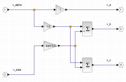
The Inverse Clarke Transform block enter image description here

Ther results are following

Stator currents enter image description here

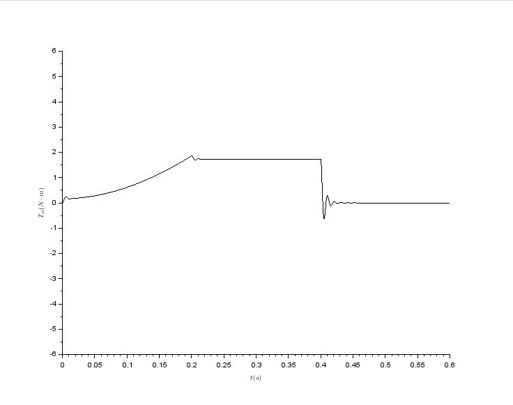
Motor torque enter image description here

Reference and actual mechanical speed enter image description here

Stator voltage in q axis enter image description here

I have doubts about correctness of my model due to the fact that the actual motor speed differs from the reference speed. I expected that they will equal because of the modeled machine is a synchronous motor. Does anybody know where I did a mistake? Thanks in advance for any suggestions.

I have met with a scalar control algorithm for a permanent magnet synchronous motor. I haven´t heard about it before so I decided to develop a dynamic model to further analyze this control algorithm. Unfortunatelly I haven´t got the Matlab with the SimPowerSystems library so I decided to create this model in Scilab.

I have been using below given equations for PMSM simulation:

\$\frac{\mathrm{d}i_d}{\mathrm{d}t} = \frac{1}{L_d}(u_d-R\cdot i_q+L_q\cdot\omega_e\cdot i_q), \\ \frac{\mathrm{d}i_q}{\mathrm{d}t} = \frac{1}{L_q}(u_q-R\cdot i_q-L_d\cdot\omega_e\cdot i_d - \omega_e\cdot\psi_m), \\ \frac{\mathrm{d}\omega_m}{\mathrm{d}t} = \frac{1}{J}(1.5\cdot p\cdot\psi_m\cdot i_q - T_l),\\ \omega_e = p\cdot\omega_m\$

where \$p\$ is number of pole pairs

The parameters of the model:

\$L_d = 1.365\cdot10^{-3}\,H \\ L_q = 1.365\cdot10^{-3}\,H \\ R = 0.416\,\Omega \\ \psi_m = 0.166\,Wb \\ p = 2 \\ J = 3.4\cdot10^{-4}\,kg\cdot m^2 \\ kF= \frac{3.2}{(2\cdot\pi\cdot 1200/60)^2}\,\frac{N\cdot m}{(rad\cdot s^{-1})^2}\$

Here is my overall simulation model enter image description here

The motor is loaded by below given torque

\$T_l = kF\cdot\omega^2\$ which is removed in step wise manner at \$t=0.4\,s\$

The U/f block enter image description here

The PMSM Model block enter image description here

The Inverse Park Transform block enter image description here

The Inverse Clarke Transform block enter image description here

Ther results are following

Stator currents enter image description here

Motor torque enter image description here

Reference and actual mechanical speed enter image description here

Stator voltage in q axis enter image description here

I have doubts about correctness of my model due to the fact that the actual motor speed differs from the reference speed. I expected that they will equal because of the modeled machine is a synchronous motor. Does anybody know where I did a mistake? Thanks in advance for any suggestions.

I have met with a scalar control algorithm for a permanent magnet synchronous motor. I haven´t heard about it before so I decided to develop a dynamic model to further analyze this control algorithm. Unfortunatelly I haven´t got the Matlab with the SimPowerSystems library so I decided to create this model in Scilab.

I have been using below given equations for PMSM simulation:

\$\frac{\mathrm{d}i_d}{\mathrm{d}t} = \frac{1}{L_d}\cdot(u_d-R\cdot i_q+L_q\cdot\omega_e\cdot i_q), \\ \frac{\mathrm{d}i_q}{\mathrm{d}t} = \frac{1}{L_q}\cdot(u_q-R\cdot i_q-L_d\cdot\omega_e\cdot i_d - \omega_e\cdot\psi_m), \\ \frac{\mathrm{d}\omega_m}{\mathrm{d}t} = \frac{1}{J}\cdot(1.5\cdot p\cdot\psi_m\cdot i_q - T_l),\\ \omega_e = p\cdot\omega_m\$

where \$p\$ is number of pole pairs

The parameters of the model:

\$L_d = 1.365\cdot10^{-3}\,H \\ L_q = 1.365\cdot10^{-3}\,H \\ R = 0.416\,\Omega \\ \psi_m = 0.166\,Wb \\ p = 2 \\ J = 3.4\cdot10^{-4}\,kg\cdot m^2 \\ kF= \frac{3.2}{(2\cdot\pi\cdot\frac{1200}{60})^2}\,\frac{N\cdot m}{(rad\cdot s^{-1})^2}\$

Here is my overall simulation model enter image description here

The motor is loaded by below given torque

\$T_l = kF\cdot\omega^2\$ which is removed in step wise manner at \$t=0.4\,s\$

The U/f block enter image description here

The PMSM Model block enter image description here

The Inverse Park Transform block enter image description here

The Inverse Clarke Transform block enter image description here

Ther results are following

Stator currents enter image description here

Motor torque enter image description here

Reference and actual mechanical speed enter image description here

Stator voltage in q axis enter image description here

I have doubts about correctness of my model due to the fact that the actual motor speed differs from the reference speed. I expected that they will equal because of the modeled machine is a synchronous motor. Does anybody know where I did a mistake? Thanks in advance for any suggestions.

edited tags
Source Link
Steve
  • 1.1k
  • 9
  • 28

I have met with a scalar control algorithm for a permanent magnet synchronous motor. I haven´t heard about it before so I decided to develop a dynamic model to further analyze this control algorithm. Unfortunatelly I haven´t got the Matlab with the SimPowerSystems library so I decided to create this model in Scilab.

I have been using below given equations for PMSM simulation:

\$\frac{\mathrm{d}i_d}{\mathrm{d}t} = \frac{1}{L_d}(u_d-R\cdot i_q+L_q\cdot\omega_e\cdot i_q), \\ \frac{\mathrm{d}i_q}{\mathrm{d}t} = \frac{1}{L_q}(u_q-R\cdot i_q-L_d\cdot\omega_e\cdot i_d - \omega_e\cdot\psi_m), \\ \frac{\mathrm{d}\omega_m}{\mathrm{d}t} = \frac{1}{J}(1.5\cdotp\cdot\psi_m\cdot i_q - T_l),\\ \omega_e = p\cdot\omega_m\$\$\frac{\mathrm{d}i_d}{\mathrm{d}t} = \frac{1}{L_d}(u_d-R\cdot i_q+L_q\cdot\omega_e\cdot i_q), \\ \frac{\mathrm{d}i_q}{\mathrm{d}t} = \frac{1}{L_q}(u_q-R\cdot i_q-L_d\cdot\omega_e\cdot i_d - \omega_e\cdot\psi_m), \\ \frac{\mathrm{d}\omega_m}{\mathrm{d}t} = \frac{1}{J}(1.5\cdot p\cdot\psi_m\cdot i_q - T_l),\\ \omega_e = p\cdot\omega_m\$

where \$p\$ is number of pole pairs

The parameters of the model:

\$L_d = 1.365\cdot10^{-3}\,H \\ L_q = 1.365\cdot10^{-3}\,H \\ R = 0.416\,\Omega \\ \psi_m = 0.166\,Wb \\ p = 2 \\ J = 3.4\cdot10^{-4}\,kg\cdot m^2 \\ kF= \frac{3.2}{(2\cdot\pi\cdot 1200/60)^2}\,\frac{N\cdot m}{(rad\cdot s^{-1})^2}\$

Here is my overall simulation model enter image description here

The motor is loaded by below given torque

\$T_l = kF\cdot\omega^2\$ which is removed in step wise manner at \$t=0.4\,s\$

The U/f block enter image description here

The PMSM Model block enter image description here

The Inverse Park Transform block enter image description here

The Inverse Clarke Transform block enter image description here

Ther results are following

Stator currents enter image description here

Motor torque enter image description here

Reference and actual mechanical speed enter image description here

Stator voltage in q axis enter image description here

I have doubts about correctness of my model due to the fact that the actual motor speed differs from the reference speed. I expected that they will equal because of the modeled machine is a synchronous motor. Does anybody know where I did a mistake? Thanks in advance for any suggestions.
I have met with a scalar control algorithm for a permanent magnet synchronous motor. I haven´t heard about it before so I decided to develop a dynamic model to further analyze this control algorithm. Unfortunatelly I haven´t got the Matlab with the SimPowerSystems library so I decided to create this model in Scilab.

I have been using below given equations for PMSM simulation:

\$\frac{\mathrm{d}i_d}{\mathrm{d}t} = \frac{1}{L_d}(u_d-R\cdot i_q+L_q\cdot\omega_e\cdot i_q), \\ \frac{\mathrm{d}i_q}{\mathrm{d}t} = \frac{1}{L_q}(u_q-R\cdot i_q-L_d\cdot\omega_e\cdot i_d - \omega_e\cdot\psi_m), \\ \frac{\mathrm{d}\omega_m}{\mathrm{d}t} = \frac{1}{J}(1.5\cdotp\cdot\psi_m\cdot i_q - T_l),\\ \omega_e = p\cdot\omega_m\$

where \$p\$ is number of pole pairs

The parameters of the model:

\$L_d = 1.365\cdot10^{-3}\,H \\ L_q = 1.365\cdot10^{-3}\,H \\ R = 0.416\,\Omega \\ \psi_m = 0.166\,Wb \\ p = 2 \\ J = 3.4\cdot10^{-4}\,kg\cdot m^2 \\ kF= \frac{3.2}{(2\cdot\pi\cdot 1200/60)^2}\,\frac{N\cdot m}{(rad\cdot s^{-1})^2}\$

Here is my overall simulation model enter image description here

The motor is loaded by below given torque

\$T_l = kF\cdot\omega^2\$ which is removed in step wise manner at \$t=0.4\,s\$

The U/f block enter image description here

The PMSM Model block enter image description here

The Inverse Park Transform block enter image description here

The Inverse Clarke Transform block enter image description here

Ther results are following

Stator currents enter image description here

Motor torque enter image description here

Reference and actual mechanical speed enter image description here

Stator voltage in q axis enter image description here

I have doubts about correctness of my model due to the fact that the actual motor speed differs from the reference speed. I expected that they will equal because of the modeled machine is a synchronous motor. Does anybody know where I did a mistake? Thanks in advance for any suggestions.

I have met with a scalar control algorithm for a permanent magnet synchronous motor. I haven´t heard about it before so I decided to develop a dynamic model to further analyze this control algorithm. Unfortunatelly I haven´t got the Matlab with the SimPowerSystems library so I decided to create this model in Scilab.

I have been using below given equations for PMSM simulation:

\$\frac{\mathrm{d}i_d}{\mathrm{d}t} = \frac{1}{L_d}(u_d-R\cdot i_q+L_q\cdot\omega_e\cdot i_q), \\ \frac{\mathrm{d}i_q}{\mathrm{d}t} = \frac{1}{L_q}(u_q-R\cdot i_q-L_d\cdot\omega_e\cdot i_d - \omega_e\cdot\psi_m), \\ \frac{\mathrm{d}\omega_m}{\mathrm{d}t} = \frac{1}{J}(1.5\cdot p\cdot\psi_m\cdot i_q - T_l),\\ \omega_e = p\cdot\omega_m\$

where \$p\$ is number of pole pairs

The parameters of the model:

\$L_d = 1.365\cdot10^{-3}\,H \\ L_q = 1.365\cdot10^{-3}\,H \\ R = 0.416\,\Omega \\ \psi_m = 0.166\,Wb \\ p = 2 \\ J = 3.4\cdot10^{-4}\,kg\cdot m^2 \\ kF= \frac{3.2}{(2\cdot\pi\cdot 1200/60)^2}\,\frac{N\cdot m}{(rad\cdot s^{-1})^2}\$

Here is my overall simulation model enter image description here

The motor is loaded by below given torque

\$T_l = kF\cdot\omega^2\$ which is removed in step wise manner at \$t=0.4\,s\$

The U/f block enter image description here

The PMSM Model block enter image description here

The Inverse Park Transform block enter image description here

The Inverse Clarke Transform block enter image description here

Ther results are following

Stator currents enter image description here

Motor torque enter image description here

Reference and actual mechanical speed enter image description here

Stator voltage in q axis enter image description here

I have doubts about correctness of my model due to the fact that the actual motor speed differs from the reference speed. I expected that they will equal because of the modeled machine is a synchronous motor. Does anybody know where I did a mistake? Thanks in advance for any suggestions.

edited tags
Link
Steve
  • 1.1k
  • 9
  • 28
Source Link
Steve
  • 1.1k
  • 9
  • 28
Loading