added 434 characters in body
Source Link
stevenvh
  • 146.6k
  • 21
  • 460
  • 669

I would simply place a capacitor across the InAmp's inputs, or rather a couple of them in parallel, like for instance 10 nF, 100 nF and 10 µF. These should short-circuit any RF signals and 50 Hz noise picked up by the cable. Ignoring the 10 µF for HF (it won't perform that well at high frequencies), 110 nF is 0.14 Ω at 10 MHz, which should take almost all energy out of it. The 10 µF should take care of lower frequencies.

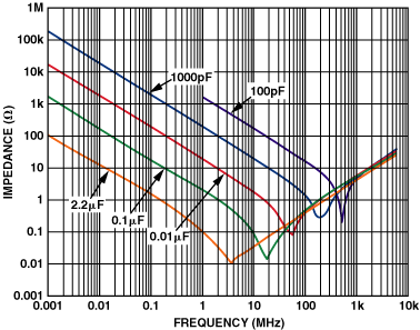
In theory the parallel capacitors should be just one larger capacitor, but their impedance rises again at higher frequencies due to ESL (Equivalent Series Inductance), and the poles are different for different capacitances, like this graph shows:
enter image description here

By placing different capacitances in parallel you take advantage of the poles for each of them.

I would simply place a capacitor across the InAmp's inputs, or rather a couple of them in parallel, like for instance 10 nF, 100 nF and 10 µF. These should short-circuit any RF signals and 50 Hz noise picked up by the cable. Ignoring the 10 µF for HF (it won't perform that well at high frequencies), 110 nF is 0.14 Ω at 10 MHz, which should take almost all energy out of it. The 10 µF should take care of lower frequencies.

I would simply place a capacitor across the InAmp's inputs, or rather a couple of them in parallel, like for instance 10 nF, 100 nF and 10 µF. These should short-circuit any RF signals and 50 Hz noise picked up by the cable. Ignoring the 10 µF for HF (it won't perform that well at high frequencies), 110 nF is 0.14 Ω at 10 MHz, which should take almost all energy out of it. The 10 µF should take care of lower frequencies.

In theory the parallel capacitors should be just one larger capacitor, but their impedance rises again at higher frequencies due to ESL (Equivalent Series Inductance), and the poles are different for different capacitances, like this graph shows:

enter image description here

By placing different capacitances in parallel you take advantage of the poles for each of them.

Source Link
stevenvh
  • 146.6k
  • 21
  • 460
  • 669

I would simply place a capacitor across the InAmp's inputs, or rather a couple of them in parallel, like for instance 10 nF, 100 nF and 10 µF. These should short-circuit any RF signals and 50 Hz noise picked up by the cable. Ignoring the 10 µF for HF (it won't perform that well at high frequencies), 110 nF is 0.14 Ω at 10 MHz, which should take almost all energy out of it. The 10 µF should take care of lower frequencies.