1kHz PWM ...my opto-coupler should be fast enough, so that it can transmit the narrowest pulse (1% duty cycle), which has a duration of 1% * (1/1000) = 10 μs. Consequently, I need to have: tr + tf < 10 μs
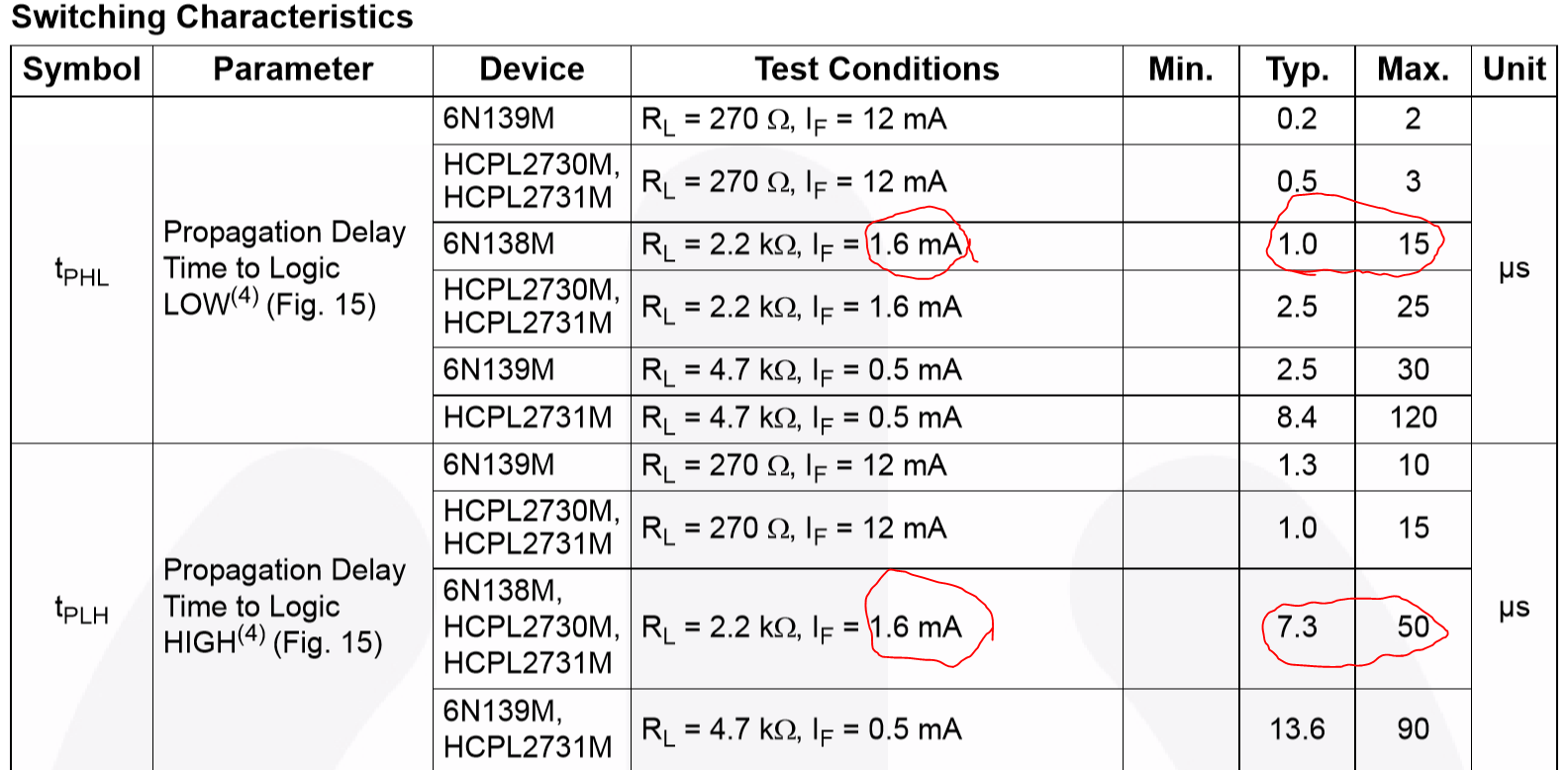
Correct, but I would suggest you need delay times (not rise and fall times) much much less than 10us. You need to decide what fidelity you need for the output waveform. If you use the 6N138 then the delay times combined could be 65us worst case. At this you would get no viable PWM signal below about 6%. Even using the 'Typical' number, you could expect delay times to be 8.3us so severely distorting small PWM values.
This has nothing to do with the rise and fall times of the output, which are related to the load (Rl) and the capacitance of the load.
The datasheet shows:

From the above data I would suggest that the 6N138 would NOT be suitable for your application.
While there are many opto-isolators that might (when you decide how much distortion and edge delay you can tolerate) fill the bill, I'll suggest what might be a high end solution for you as an example.
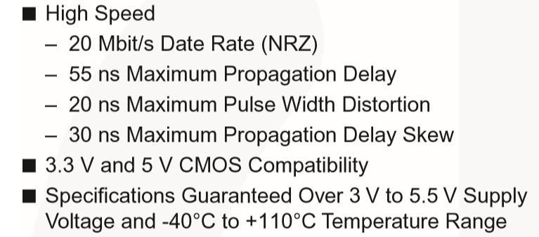
The On Semiconductor FOD8071 has very low delay values and a true digital output signal (not open-collector). This device is based on a photodiode receiver, which is invariably much faster than any transistor based coupler.
The spec snapshot is:

This type of device ensures that the accuracy of your input signal PWM signal is reflected in the output.
The input threshold current is about 3.5mA for this device, so selecting an input current range of 5-10mA should be good place to start. Your MCU output should be able to sink 10mA and with the Vf of the LED being in the 1-1.8V range then at a 3.3V MCU supply a 230 Ohm resistor would be adequate to define the input LED current. Over the full Vf range this would ensure 6.5-10mA LED current.
You should research opto-isolators in the 1Mbps and above range to get reasonable PWM distortion values. With 1Mbps capability you would expect delay times in the 200-600ns range which may be adequate for your purposes. Perhaps start with a search like this on Digikey.
Update: Understanding the turn on and turn off delays (you can call them rise time and fall times if you like, but they appear as edge delays in the circuit).
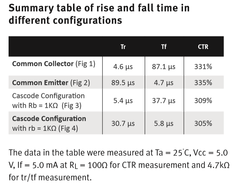
This application note on the very problem being discussed is relevant and performed at 1kHz square wave (equivalent to a PWM 50% signal).
They used a very common opto-isolator (PS2501-1) and characterized the turn on and turn off delays as rise and fall times. I disagree with that terminology, but the note aptly shows the delay in producing an edge assuming voltage sensitive logic on the output load.
The datasheet for the opto quotes tr/tf at 3us and 5us respectively, but the app note shows the measured values at about 5us and 90us for tr/tf depending on output configuration.

They then attempt to speed up the circuitry adding a more complex output configuration (cascode), but even then only achieve 6us and 32us for tr/tf in their note.
This shows that this type of opto (transistor based) is unsuitable where you want to assure that the output signal accurately follows the input signal.
Using an opto based on a photo-diode is invariably much faster, has almost symmetrical delays and is not dependent of high CTR.


