added 168 characters in body
Source Link

I am looking for an LED driver circuit that would illuminate when a voltage is at zero, and which would gradually shut off as a voltage rises to 3.3v, with a (somewhat) direct relationship between brightness and voltage level.

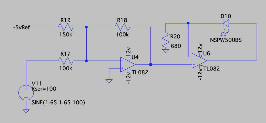
I have already designed this circuit using an inverting op amp to invert and offset the control voltage signal with a negative reference, and then a second op amp to drive the LED using the feedback path.

I am hoping that someone might know of a simpler design, that would be lower cost and fewer parts. As it stands, this will cost me about $0.30 and uses 5 parts (not counting the LED itself). I need 16 of these in a single circuit, and I was hoping to be able to reduce the cost to below $2 total, ideally below $1

Inverting LED Driver Circuit1

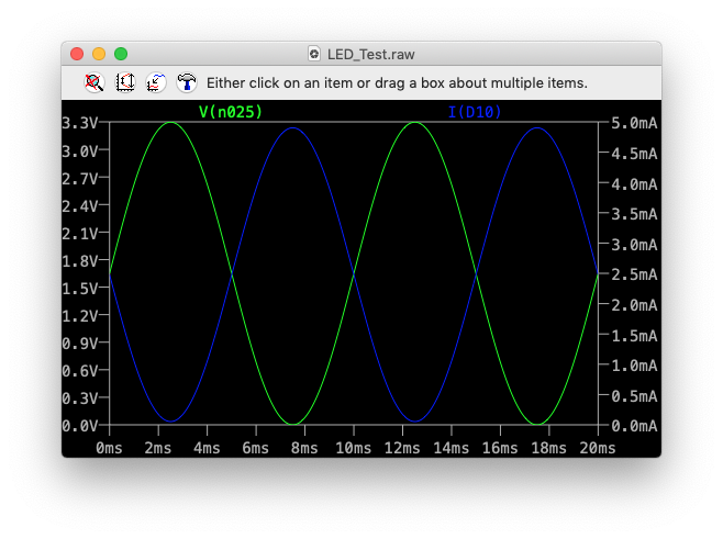
And here is the signal analysis, where the Green line is the 0-3v3 control signal, and the Blue line is the current used by the LED itself.

enter image description here

UPDATE 1:

One additional constraint I forgot to mention is the control input must be high impedance, as that signal will be needed for other purposes as well

I am looking for an LED driver circuit that would illuminate when a voltage is at zero, and which would gradually shut off as a voltage rises to 3.3v, with a (somewhat) direct relationship between brightness and voltage level.

I have already designed this circuit using an inverting op amp to invert and offset the control voltage signal with a negative reference, and then a second op amp to drive the LED using the feedback path.

I am hoping that someone might know of a simpler design, that would be lower cost and fewer parts. As it stands, this will cost me about $0.30 and uses 5 parts (not counting the LED itself). I need 16 of these in a single circuit, and I was hoping to be able to reduce the cost to below $2 total, ideally below $1

Inverting LED Driver Circuit1

And here is the signal analysis, where the Green line is the 0-3v3 control signal, and the Blue line is the current used by the LED itself.

enter image description here

UPDATE 1:

One additional constraint I forgot to mention is the control input must be high impedance, as that signal will be needed for other purposes as well
added 124 characters in body
Source Link

I am looking for an LED driver circuit that would illuminate when a voltage is at zero, and which would gradually shut off as a voltage rises to 3.3v, with a (somewhat) direct relationship between brightness and voltage level.

I have already designed this circuit using an inverting op amp to invert and offset the control voltage signal with a negative reference, and then a second op amp to drive the LED using the feedback path.

I am hoping that someone might know of a simpler design, that would be lower cost and fewer parts. As it stands, this will cost me about $0.30 and uses 5 parts (not counting the LED itself). I need 16 of these in a single circuit, and I was hoping to be able to reduce the cost to below $2 total, ideally below $1

Inverting LED Driver Circuit1

And here is the signal analysis, where the Green line is the 0-3v3 control signal, and the Blue line is the current used by the LED itself.

enter image description here

I am looking for an LED driver circuit that would illuminate when a voltage is at zero, and which would gradually shut off as a voltage rises to 3.3v, with a (somewhat) direct relationship between brightness and voltage level.

I have already designed this circuit using an inverting op amp to invert and offset the control voltage signal with a negative reference, and then a second op amp to drive the LED using the feedback path.

I am hoping that someone might know of a simpler design, that would be lower cost and fewer parts. As it stands, this will cost me about $0.30 and uses 5 parts (not counting the LED itself)

Inverting LED Driver Circuit1

And here is the signal analysis, where the Green line is the 0-3v3 control signal, and the Blue line is the current used by the LED itself.

enter image description here

I am looking for an LED driver circuit that would illuminate when a voltage is at zero, and which would gradually shut off as a voltage rises to 3.3v, with a (somewhat) direct relationship between brightness and voltage level.

I have already designed this circuit using an inverting op amp to invert and offset the control voltage signal with a negative reference, and then a second op amp to drive the LED using the feedback path.

I am hoping that someone might know of a simpler design, that would be lower cost and fewer parts. As it stands, this will cost me about $0.30 and uses 5 parts (not counting the LED itself). I need 16 of these in a single circuit, and I was hoping to be able to reduce the cost to below $2 total, ideally below $1

Inverting LED Driver Circuit1

And here is the signal analysis, where the Green line is the 0-3v3 control signal, and the Blue line is the current used by the LED itself.

enter image description here

Source Link

Inverted LED driver circuit

I am looking for an LED driver circuit that would illuminate when a voltage is at zero, and which would gradually shut off as a voltage rises to 3.3v, with a (somewhat) direct relationship between brightness and voltage level.

I have already designed this circuit using an inverting op amp to invert and offset the control voltage signal with a negative reference, and then a second op amp to drive the LED using the feedback path.

I am hoping that someone might know of a simpler design, that would be lower cost and fewer parts. As it stands, this will cost me about $0.30 and uses 5 parts (not counting the LED itself)

Inverting LED Driver Circuit1

And here is the signal analysis, where the Green line is the 0-3v3 control signal, and the Blue line is the current used by the LED itself.

enter image description here