added 642 characters in body
Source Link
Transistor
  • 180.3k
  • 14
  • 193
  • 417

Wikipedia: ... for the case of a hypothetical 1 mA, 500 Ω movement

This means that the meter reads full scale when 1 mA is flowing through it. The voltage across the meter will be \$ V = IR = 1m \cdot 500 = 500 \ \text {mV} \$. So it will read full scale if connected across a 500 mV voltage source too.

schematic

simulate this circuit – Schematic created using CircuitLab

Figure 1. The example meter has an internal resistance of 500 Ω and will read full scale with 1 mA through it.

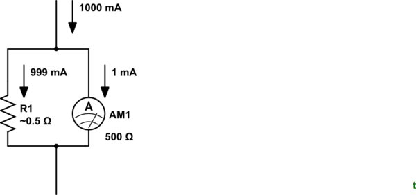
... on a 1 A range, the shunt resistance would be just over 0.5 Ω.
schematic

simulate this circuit

Figure 2. R1 "shunts" most of the current around the ammeter.

To measure 1 A without damage to the meter we need to shunt 499 mA around the meter while 1 mA runs through it. We have already calculated that the voltage drop across the meter will be 500 mV at full scale so we can calculate R1 as $$ R_1 = \frac {V}{I} = \frac {0.5}{0.999} = 0.5005 \ \Omega $$

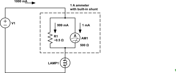
The combined meter and shunt is always wired in series with the circuit being measured.
schematic

simulate this circuit

Figure 3. Correct measurement technique.

From the comments:

You need to connect your multimeter in series when you are measuring current. – The Photon

But this article talks of something parallel – Shlok Vaibhav

It is describing the meter being in parallel to the shunt which is in series with the circuit being measured. Hopefully this is clear now.

Wikipedia: ... for the case of a hypothetical 1 mA, 500 Ω movement

This means that the meter reads full scale when 1 mA is flowing through it. The voltage across the meter will be \$ V = IR = 1m \cdot 500 = 500 \ \text {mV} \$. So it will read full scale if connected across a 500 mV voltage source too.

schematic

simulate this circuit – Schematic created using CircuitLab

Figure 1. The example meter has an internal resistance of 500 Ω and will read full scale with 1 mA through it.

... on a 1 A range, the shunt resistance would be just over 0.5 Ω.

schematic

simulate this circuit

Figure 2. R1 "shunts" most of the current around the ammeter.

To measure 1 A without damage to the meter we need to shunt 499 mA around the meter while 1 mA runs through it. We have already calculated that the voltage drop across the meter will be 500 mV at full scale so we can calculate R1 as $$ R_1 = \frac {V}{I} = \frac {0.5}{0.999} = 0.5005 \ \Omega $$

The combined meter and shunt is always wired in series with the circuit being measured.

schematic

simulate this circuit

Figure 3. Correct measurement technique.

From the comments:

You need to connect your multimeter in series when you are measuring current. – The Photon

But this article talks of something parallel – Shlok Vaibhav

It is describing the meter being in parallel to the shunt which is in series with the circuit being measured. Hopefully this is clear now.

Source Link
Transistor
  • 180.3k
  • 14
  • 193
  • 417

Wikipedia: ... for the case of a hypothetical 1 mA, 500 Ω movement

This means that the meter reads full scale when 1 mA is flowing through it. The voltage across the meter will be \$ V = IR = 1m \cdot 500 = 500 \ \text {mV} \$. So it will read full scale if connected across a 500 mV voltage source too.

schematic

simulate this circuit – Schematic created using CircuitLab

Figure 1. The example meter has an internal resistance of 500 Ω and will read full scale with 1 mA through it.

... on a 1 A range, the shunt resistance would be just over 0.5 Ω.

schematic

simulate this circuit

Figure 2. R1 "shunts" most of the current around the ammeter.

To measure 1 A without damage to the meter we need to shunt 499 mA around the meter while 1 mA runs through it. We have already calculated that the voltage drop across the meter will be 500 mV at full scale so we can calculate R1 as $$ R_1 = \frac {V}{I} = \frac {0.5}{0.999} = 0.5005 \ \Omega $$

The combined meter and shunt is always wired in series with the circuit being measured.