Simplified the final question
Source Link

I need to build a circuit that accepts a 4-bit number and turns on a LED (representing an error) if the given number is higher than 9.

As I understood, it should represent an "error display for a BCD counter". Since a BCD accepts a number of 4 bits (0-15) but it only counts from 0-9, I should turn on a LED that represents the presence of an error on the counter.

So, I followed the steps below:

  1. Built the truth table;
  2. Built the expression based on the truth table;
  3. Built the Karnaugh Map;
  4. Built the simplified expression from the Karnaugh Map;

1. Building the Truth Table

Note: the X column represents the output that shows an error (i.e. the LED)

enter image description here


2. Building the expression based on the Truth Table

So, based on the Truth Table, I got the following expressions:

Note: consider the (!X) as a NOT X

(D)(!C)(B)(!A) + (D)(!C)(B)(A) + (D)(C)(!B)(!A) + (D)(C)(!B)(A) + (D)(C)(B)(!A) + (D)(C)(B)(A)


3. Building the Karnaugh Map

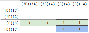
enter image description here

So, as you guys can see, I found two quartets.


4. Building the simplified expression from the Karnaugh Map

As I found two quartets, this is the final expression I found:

(DC) + (DB)


The conclusion and the final question

So, based on the simplified expression, I can see that the port A doesn't matter atafter all.

So these steps, supposing I have a circuit that counts in BCD. It was done previously by someone else. It accepts a 4-bit number and then ouputs another 4-bit number.

It means that iftried to apply the number ranges between 0-9Truth Table values into my simplified expression (0000-1001), then the output isignoring the same. HoweverA column, ifas the number ranges between 10-15 (1010-1111simplified expression doesn't contain it), so the output ranges between 0000-0101. It seems to be correct after all.

My question is: if I need to build an extra circuit to integrate with this BCD one (remember: created by

Let's suppose someone else), which receives 4-bit numbersget close to me and turns on a LED in case there is an error (number is higher than 9), should I just ignore the A input? Since the A input is not considered on thesays:

"I've built a BCD counter. It should only count from 0 to 9. If a number higher than 9 is given, then there is an error. I need YOU to build ANOTHER circuit. I'll give you the 4-bit number that entered on my circuit and then you need to show an error in case this number is higher than 9."

Considering my final expression, (DC) + (DB)., should I just ignore the port A, since there is no A in my final simplified expression? Does it mean I can just leave A without being connected to any wire?

I need to build a circuit that accepts a 4-bit number and turns on a LED (representing an error) if the given number is higher than 9.

As I understood, it should represent an "error display for a BCD counter". Since a BCD accepts a number of 4 bits (0-15) but it only counts from 0-9, I should turn on a LED that represents the presence of an error on the counter.

So, I followed the steps below:

  1. Built the truth table;
  2. Built the expression based on the truth table;
  3. Built the Karnaugh Map;
  4. Built the simplified expression from the Karnaugh Map;

1. Building the Truth Table

Note: the X column represents the output that shows an error (i.e. the LED)

enter image description here


2. Building the expression based on the Truth Table

So, based on the Truth Table, I got the following expressions:

Note: consider the (!X) as a NOT X

(D)(!C)(B)(!A) + (D)(!C)(B)(A) + (D)(C)(!B)(!A) + (D)(C)(!B)(A) + (D)(C)(B)(!A) + (D)(C)(B)(A)


3. Building the Karnaugh Map

enter image description here

So, as you guys can see, I found two quartets.


4. Building the simplified expression from the Karnaugh Map

As I found two quartets, this is the final expression I found:

(DC) + (DB)


The conclusion and the final question

So, based on the simplified expression, I can see that the port A doesn't matter at all.

So, supposing I have a circuit that counts in BCD. It was done previously by someone else. It accepts a 4-bit number and then ouputs another 4-bit number.

It means that if the number ranges between 0-9 (0000-1001), then the output is the same. However, if the number ranges between 10-15 (1010-1111), so the output ranges between 0000-0101.

My question is: if I need to build an extra circuit to integrate with this BCD one (remember: created by someone else), which receives 4-bit numbers and turns on a LED in case there is an error (number is higher than 9), should I just ignore the A input? Since the A input is not considered on the final expression (DC) + (DB).

I need to build a circuit that accepts a 4-bit number and turns on a LED (representing an error) if the given number is higher than 9.

As I understood, it should represent an "error display for a BCD counter". Since a BCD accepts a number of 4 bits (0-15) but it only counts from 0-9, I should turn on a LED that represents the presence of an error on the counter.

So, I followed the steps below:

  1. Built the truth table;
  2. Built the expression based on the truth table;
  3. Built the Karnaugh Map;
  4. Built the simplified expression from the Karnaugh Map;

1. Building the Truth Table

Note: the X column represents the output that shows an error (i.e. the LED)

enter image description here


2. Building the expression based on the Truth Table

So, based on the Truth Table, I got the following expressions:

Note: consider the (!X) as a NOT X

(D)(!C)(B)(!A) + (D)(!C)(B)(A) + (D)(C)(!B)(!A) + (D)(C)(!B)(A) + (D)(C)(B)(!A) + (D)(C)(B)(A)


3. Building the Karnaugh Map

enter image description here

So, as you guys can see, I found two quartets.


4. Building the simplified expression from the Karnaugh Map

As I found two quartets, this is the final expression I found:

(DC) + (DB)


The conclusion and the final question

So, after all these steps, I tried to apply the Truth Table values into my simplified expression (ignoring the A column, as the simplified expression doesn't contain it). It seems to be correct after all.

My question is:

Let's suppose someone get close to me and says:

"I've built a BCD counter. It should only count from 0 to 9. If a number higher than 9 is given, then there is an error. I need YOU to build ANOTHER circuit. I'll give you the 4-bit number that entered on my circuit and then you need to show an error in case this number is higher than 9."

Considering my final expression, (DC) + (DB), should I just ignore the port A, since there is no A in my final simplified expression? Does it mean I can just leave A without being connected to any wire?
Source Link

Can a circuit that shows an error if a 4-bit number is higher than 9 be simplified to "(DC) + (DB)"?

I need to build a circuit that accepts a 4-bit number and turns on a LED (representing an error) if the given number is higher than 9.

As I understood, it should represent an "error display for a BCD counter". Since a BCD accepts a number of 4 bits (0-15) but it only counts from 0-9, I should turn on a LED that represents the presence of an error on the counter.

So, I followed the steps below:

  1. Built the truth table;
  2. Built the expression based on the truth table;
  3. Built the Karnaugh Map;
  4. Built the simplified expression from the Karnaugh Map;

1. Building the Truth Table

Note: the X column represents the output that shows an error (i.e. the LED)

enter image description here


2. Building the expression based on the Truth Table

So, based on the Truth Table, I got the following expressions:

Note: consider the (!X) as a NOT X

(D)(!C)(B)(!A) + (D)(!C)(B)(A) + (D)(C)(!B)(!A) + (D)(C)(!B)(A) + (D)(C)(B)(!A) + (D)(C)(B)(A)


3. Building the Karnaugh Map

enter image description here

So, as you guys can see, I found two quartets.


4. Building the simplified expression from the Karnaugh Map

As I found two quartets, this is the final expression I found:

(DC) + (DB)


The conclusion and the final question

So, based on the simplified expression, I can see that the port A doesn't matter at all.

So, supposing I have a circuit that counts in BCD. It was done previously by someone else. It accepts a 4-bit number and then ouputs another 4-bit number.

It means that if the number ranges between 0-9 (0000-1001), then the output is the same. However, if the number ranges between 10-15 (1010-1111), so the output ranges between 0000-0101.

My question is: if I need to build an extra circuit to integrate with this BCD one (remember: created by someone else), which receives 4-bit numbers and turns on a LED in case there is an error (number is higher than 9), should I just ignore the A input? Since the A input is not considered on the final expression (DC) + (DB).