added 480 characters in body
Source Link

Using a regulated current source to light them, wire the LEDs in series and short out the segment which you want to be dark.
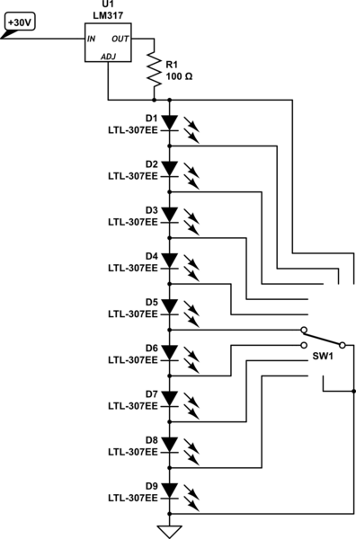
schematic

simulate this circuit – Schematic created using CircuitLab

You can possibly use a buck-boost converter to make the 30V if you don't already have a suitable voltage.

Here's a simple way to build one using a LM2596S module:

  1. Remove the potentiometer and both large capacitors
  2. Connect one of the salvaged capacitors between +in and +out (positive to +in), and fit a 1uF ceramic capacitor where the output capacitor was.
  3. Connect a 100 ohm resistor from the -output to the centre potentiometer terminal.

Modified in this way, it will create a negative voltage on the -out terminals and act as a 12.5mA current sink at the centre potentiometer terminal (with source at +out) if power is applied between +in and +out.

schematic

simulate this circuit

or a XL6009 buck-boost module can be modified. this time just remove the potentiometer and add a 100 ohm resistor, connec 3-30V to the nirmal input terminals and connect the LED string to the output and resistor.

schematic

simulate this circuit

Using a regulated current source to light them, wire the LEDs in series and short out the segment which you want to be dark.

schematic

simulate this circuit – Schematic created using CircuitLab

You can possibly use a buck-boost converter to make the 30V if you don't already have a suitable voltage.

Here's a simple way to build one using a LM2596S module:

  1. Remove the potentiometer and both large capacitors
  2. Connect one of the salvaged capacitors between +in and +out (positive to +in), and fit a 1uF ceramic capacitor where the output capacitor was.
  3. Connect a 100 ohm resistor from the -output to the centre potentiometer terminal.

Modified in this way, it will create a negative voltage on the -out terminals and act as a 12.5mA current sink at the centre potentiometer terminal (with source at +out) if power is applied between +in and +out.

schematic

simulate this circuit

or a XL6009 buck-boost module can be modified. this time just remove the potentiometer and add a 100 ohm resistor, connec 3-30V to the nirmal input terminals and connect the LED string to the output and resistor.

schematic

simulate this circuit

useUsing a regulated current source to light them, wire themthe LEDs in series and short out the segemntsegment which you want to be dark.

schematic

simulate this circuit – Schematic created using CircuitLab

youYou can possibly use a buck-boost converter to make the 30V if you don't already have a suitable voltage.

here'sHere's a simple way to build one using a LM2596S module remove the potentiometer, and both large capacitors, connect one of the salvaged capacitor between +in and +out (positive to +in), fit a 1uF ceramic capacitor where the output capacitor was. connect a 100 ohms resistor from the -output to the centre potentiometer terminal.:

  1. Remove the potentiometer and both large capacitors
  2. Connect one of the salvaged capacitors between +in and +out (positive to +in), and fit a 1uF ceramic capacitor where the output capacitor was.
  3. Connect a 100 ohm resistor from the -output to the centre potentiometer terminal.

modifiedModified in this way, it will create a negative voltage on the -out terminals and act as a 12.5mA current sink at the centre potentiometer terminal (with source at +out) if power is applied between +in and +out.

schematic

simulate this circuit

use a regulated current source to light them, wire them in series and short out the segemnt you want to be dark.

schematic

simulate this circuit – Schematic created using CircuitLab

you can possibly use a buck-boost converter to make the 30V if you don't already have a suitable voltage.

here's a simple way to build one using a LM2596S module remove the potentiometer, and both large capacitors, connect one of the salvaged capacitor between +in and +out (positive to +in), fit a 1uF ceramic capacitor where the output capacitor was. connect a 100 ohms resistor from the -output to the centre potentiometer terminal.

modified in this way it will create a negative voltage on the -out terminals and act as a 12.5mA current sink at the centre potentiometer terminal (with source at +out) if power is applied between +in and +out

schematic

simulate this circuit

Using a regulated current source to light them, wire the LEDs in series and short out the segment which you want to be dark.

schematic

simulate this circuit – Schematic created using CircuitLab

You can possibly use a buck-boost converter to make the 30V if you don't already have a suitable voltage.

Here's a simple way to build one using a LM2596S module:

  1. Remove the potentiometer and both large capacitors
  2. Connect one of the salvaged capacitors between +in and +out (positive to +in), and fit a 1uF ceramic capacitor where the output capacitor was.
  3. Connect a 100 ohm resistor from the -output to the centre potentiometer terminal.

Modified in this way, it will create a negative voltage on the -out terminals and act as a 12.5mA current sink at the centre potentiometer terminal (with source at +out) if power is applied between +in and +out.

schematic

simulate this circuit

added 151 characters in body
Source Link

use a regulated current source to light them, wire them in series and short out the segemnt you want to be dark.

schematic

simulate this circuit – Schematic created using CircuitLab

you can possblipossibly use a buck-boost converter to make the 30V if you don't already have a suitable voltage.

here's a simple way to build one using a LM2596S module remove the potentiometer, and both large capacitors, connect one of the salvaged capacitor between +in and +out (positive to +in), fit a 1uF ceramic capacitor where the output capacitor was. connect a 100 ohms resistor from the -output to the centre potentiometer terminal.

modified in this way it will create a negative voltage on the -out terminals and act as a 12.5mA current sink at the centre potentiometer terminal (with source at +out) if power is applied between +in and +out

schematic

simulate this circuit

use a regulated current source to light them, wire them in series and short out the segemnt you want to be dark.

schematic

simulate this circuit – Schematic created using CircuitLab

you can possbli use a buck-boost converter to make the 30V if you don't already have a suitable voltage.

use a regulated current source to light them, wire them in series and short out the segemnt you want to be dark.

schematic

simulate this circuit – Schematic created using CircuitLab

you can possibly use a buck-boost converter to make the 30V if you don't already have a suitable voltage.

here's a simple way to build one using a LM2596S module remove the potentiometer, and both large capacitors, connect one of the salvaged capacitor between +in and +out (positive to +in), fit a 1uF ceramic capacitor where the output capacitor was. connect a 100 ohms resistor from the -output to the centre potentiometer terminal.

modified in this way it will create a negative voltage on the -out terminals and act as a 12.5mA current sink at the centre potentiometer terminal (with source at +out) if power is applied between +in and +out

schematic

simulate this circuit

added 151 characters in body
Source Link
Loading
Source Link
Loading