added 74 characters in body
Source Link
abc
  • 639
  • 6
  • 22
  • More turns: higher flux and therefore pulling strength at cost of higher back emf which will drown driving voltage once speed starts to rise. However, to avoid high I^2R heat losses, you may need to use thicker wire (higher volume/weight/cost). Basically, lower RPM means the stator coils will act more resistive than inductive.
  • More rotor pole pairs: closer distance to "pull in". Consider a hybrid-type stepper motor as an extreme case.
  • Larger diameter: take advantage of mechanical "leverage" of having the stator/rotor interaction occurring far from rotation axis. For a given motor volume, this video mentions that torque rises linearly with length, but quadratically with diameter. Therefore, for a given volume, you would want a "ring" motor, or at least a "pancake" motor.

See "torque motors" or "direct drive" motors, e.g. from Allied Motion, Kollmorgen, Moog, etc. They utilize all three of the above, resulting in a speed/torque curve with relatively flat, high torque in a low rpm region that quickly drops off as speed increases. "Hub motors" commonly used in e-bike applications are similar in design. From an Allied Motion torque motor:

enter image description here

As far as voltage goes, it doesn't affect the efficiency at the motor level (though maybe at the supply level) assuming the copper volume is the same and the copper thickness is "right-sized" for the voltage/current. To prove this, compare I^2R (heat loss) and NI (proportional to stator flux) for a given (V, I, R) to (2V, .5I) applied to 2x the number of 1/2 cross-sectional area windings (resulting in same copper volume), which will result in 4x the resistance.

P.S. -- Feel free to correct me if applicable.. I am still learning about this motor stuff.

  • More turns: higher flux and therefore pulling strength at cost of higher back emf which will drown driving voltage once speed starts to rise. However, to avoid high I^2R heat losses, you may need to use thicker wire (higher volume/weight/cost). Basically, lower RPM means the stator coils will act more resistive than inductive.
  • More rotor pole pairs: closer distance to "pull in". Consider a hybrid-type stepper motor as an extreme case.
  • Larger diameter: take advantage of mechanical "leverage" of having the stator/rotor interaction occurring far from rotation axis. For a given motor volume, this video mentions that torque rises linearly with length, but quadratically with diameter. Therefore, for a given volume, you would want a "ring" motor, or at least a "pancake" motor.

See "torque motors" or "direct drive" motors, e.g. from Allied Motion, Kollmorgen, Moog, etc. They utilize all three of the above, resulting in a speed/torque curve with relatively flat, high torque in a low rpm region that quickly drops off as speed increases. From an Allied Motion torque motor:

enter image description here

As far as voltage goes, it doesn't affect the efficiency at the motor level (though maybe at the supply level) assuming the copper volume is the same and the copper thickness is "right-sized" for the voltage/current. To prove this, compare I^2R (heat loss) and NI (proportional to stator flux) for a given (V, I, R) to (2V, .5I) applied to 2x the number of 1/2 cross-sectional area windings (resulting in same copper volume), which will result in 4x the resistance.

P.S. -- Feel free to correct me if applicable.. I am still learning about this motor stuff.
  • More turns: higher flux and therefore pulling strength at cost of higher back emf which will drown driving voltage once speed starts to rise. However, to avoid high I^2R heat losses, you may need to use thicker wire (higher volume/weight/cost). Basically, lower RPM means the stator coils will act more resistive than inductive.
  • More rotor pole pairs: closer distance to "pull in". Consider a hybrid-type stepper motor as an extreme case.
  • Larger diameter: take advantage of mechanical "leverage" of having the stator/rotor interaction occurring far from rotation axis. For a given motor volume, this video mentions that torque rises linearly with length, but quadratically with diameter. Therefore, for a given volume, you would want a "ring" motor, or at least a "pancake" motor.

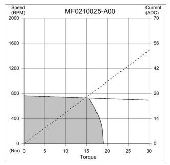
See "torque motors" or "direct drive" motors, e.g. from Allied Motion, Kollmorgen, Moog, etc. They utilize all three of the above, resulting in a speed/torque curve with relatively flat, high torque in a low rpm region that quickly drops off as speed increases. "Hub motors" commonly used in e-bike applications are similar in design. From an Allied Motion torque motor:

enter image description here

As far as voltage goes, it doesn't affect the efficiency at the motor level (though maybe at the supply level) assuming the copper volume is the same and the copper thickness is "right-sized" for the voltage/current. To prove this, compare I^2R (heat loss) and NI (proportional to stator flux) for a given (V, I, R) to (2V, .5I) applied to 2x the number of 1/2 cross-sectional area windings (resulting in same copper volume), which will result in 4x the resistance.

P.S. -- Feel free to correct me if applicable.. I am still learning about this motor stuff.

added 16 characters in body
Source Link
abc
  • 639
  • 6
  • 22
  • More turns: higher flux and therefore pulling strength at cost of higher back emf which will drown driving voltage once speed starts to rise. However, to avoid high I^2R heat losses, you may need to use thicker wire (higher volume/weight/cost). Basically, lower RPM means the stator coils will act more resistive than inductive.
  • More rotor pole pairs: closer distance to "pull in". Consider a hybrid-type stepper motor as an extreme case.
  • Larger diameter: take advantage of mechanical "leverage" of having the stator/rotor interaction occurring far from rotation axis. For a given motor volume, this video mentions that torque rises linearly with length, but quadratically with diameter. Therefore, for a given volume, you would want a "ring" motor, or at least a "pancake" motor.

See "torque motors" or "direct drive" motors, e.g. from Allied Motion, Kollmorgen, Moog, etc. They utilize all three of the above, resulting in a speed/torque curve with relatively flat, high torque in a low rpm region that quickly drops off as speed increases. From an Allied Motion torque motor:

enter image description here

As far as voltage goes, it doesn't affect the efficiency at the motor level (though maybe at the supply level) assuming the copper volume is the same and the copper thickness is "right-sized" for the voltage/current. To prove this, compare I^2R (heat loss) and NI (proportional to stator flux) for a given (V, I, R) to (2V, .5I) applied to 2x the number of 1/2 cross-sectional area windings (resulting in same copper volume), which will result in 4x the resistance.

P.S. -- Feel free to correct me if applicable.. I am still learning about this motor stuff.

  • More turns: higher flux and therefore pulling strength at cost of higher back emf which will drown driving voltage once speed starts to rise. However, to avoid high I^2R heat losses, you may need to use thicker wire (higher volume/weight/cost). Basically, lower RPM means the stator coils will act more resistive than inductive.
  • More rotor pole pairs: closer distance to "pull in". Consider a hybrid-type stepper motor as an extreme case.
  • Larger diameter: take advantage of mechanical "leverage" of having the stator/rotor interaction occurring far from rotation axis. For a given motor volume, this video mentions that torque rises linearly with length, but quadratically with diameter. Therefore, for a given volume, you would want a "ring" motor, or at least a "pancake" motor.

See "torque motors" or "direct drive" motors, e.g. from Allied Motion, Kollmorgen, Moog, etc. They utilize all three of the above, resulting in a speed/torque curve with flat, high torque in a low rpm region that quickly drops off as speed increases. From Allied Motion:

enter image description here

As far as voltage goes, it doesn't affect the efficiency at the motor level (though maybe at the supply level) assuming the copper volume is the same and the copper thickness is "right-sized" for the voltage/current. To prove this, compare I^2R (heat loss) and NI (proportional to stator flux) for a given (V, I, R) to (2V, .5I) applied to 2x the number of 1/2 cross-sectional area windings (resulting in same copper volume), which will result in 4x the resistance.

P.S. -- Feel free to correct me if applicable.. I am still learning about this motor stuff.

  • More turns: higher flux and therefore pulling strength at cost of higher back emf which will drown driving voltage once speed starts to rise. However, to avoid high I^2R heat losses, you may need to use thicker wire (higher volume/weight/cost). Basically, lower RPM means the stator coils will act more resistive than inductive.
  • More rotor pole pairs: closer distance to "pull in". Consider a hybrid-type stepper motor as an extreme case.
  • Larger diameter: take advantage of mechanical "leverage" of having the stator/rotor interaction occurring far from rotation axis. For a given motor volume, this video mentions that torque rises linearly with length, but quadratically with diameter. Therefore, for a given volume, you would want a "ring" motor, or at least a "pancake" motor.

See "torque motors" or "direct drive" motors, e.g. from Allied Motion, Kollmorgen, Moog, etc. They utilize all three of the above, resulting in a speed/torque curve with relatively flat, high torque in a low rpm region that quickly drops off as speed increases. From an Allied Motion torque motor:

enter image description here

As far as voltage goes, it doesn't affect the efficiency at the motor level (though maybe at the supply level) assuming the copper volume is the same and the copper thickness is "right-sized" for the voltage/current. To prove this, compare I^2R (heat loss) and NI (proportional to stator flux) for a given (V, I, R) to (2V, .5I) applied to 2x the number of 1/2 cross-sectional area windings (resulting in same copper volume), which will result in 4x the resistance.

P.S. -- Feel free to correct me if applicable.. I am still learning about this motor stuff.

Source Link
abc
  • 639
  • 6
  • 22

  • More turns: higher flux and therefore pulling strength at cost of higher back emf which will drown driving voltage once speed starts to rise. However, to avoid high I^2R heat losses, you may need to use thicker wire (higher volume/weight/cost). Basically, lower RPM means the stator coils will act more resistive than inductive.
  • More rotor pole pairs: closer distance to "pull in". Consider a hybrid-type stepper motor as an extreme case.
  • Larger diameter: take advantage of mechanical "leverage" of having the stator/rotor interaction occurring far from rotation axis. For a given motor volume, this video mentions that torque rises linearly with length, but quadratically with diameter. Therefore, for a given volume, you would want a "ring" motor, or at least a "pancake" motor.

See "torque motors" or "direct drive" motors, e.g. from Allied Motion, Kollmorgen, Moog, etc. They utilize all three of the above, resulting in a speed/torque curve with flat, high torque in a low rpm region that quickly drops off as speed increases. From Allied Motion:

enter image description here

As far as voltage goes, it doesn't affect the efficiency at the motor level (though maybe at the supply level) assuming the copper volume is the same and the copper thickness is "right-sized" for the voltage/current. To prove this, compare I^2R (heat loss) and NI (proportional to stator flux) for a given (V, I, R) to (2V, .5I) applied to 2x the number of 1/2 cross-sectional area windings (resulting in same copper volume), which will result in 4x the resistance.

P.S. -- Feel free to correct me if applicable.. I am still learning about this motor stuff.