Bumped by Community user
added 408 characters in body
Source Link

I am using an OpAmp to amplify an input signal that ranges from 0-3.3V to a 0-5V range. The output must only be greater than 0 if the input signal is as well.

If I understand it correctly, if +Vcc were shorted to the output, the output would be constantly at 5V. Is there a way to protect against this error case?

I have tried to come up with something or find an existing solution, but I'm rather new at electronics and maybe I'm missing the right terminology.

EDIT: I changed the schematic according to Huisman's comment.
The possible reason for a short between +Vcc and the output could be that something(a loose wire, metal shavings, etc.) physically connects the two OpAmp legs, that there is a break between the tracks on the pcb, or anything else, really. For safety considerations I'm supposed to assume a short occurs, no matter how it actually happens.
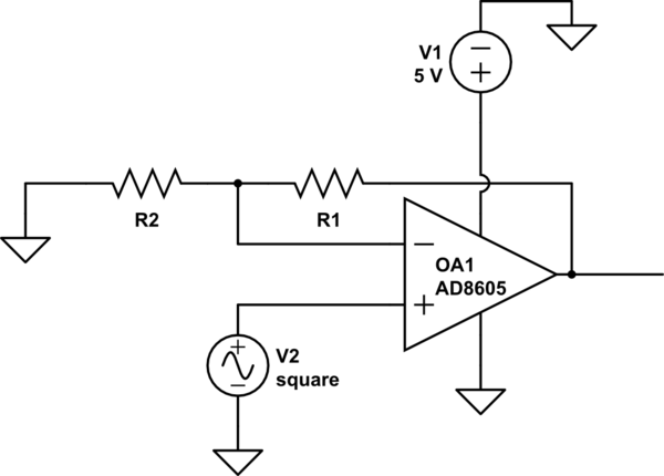
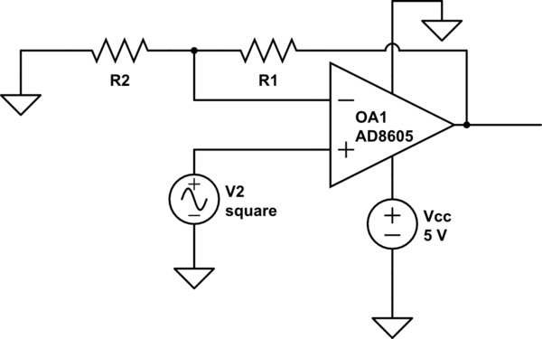
schematicschematic

simulate this circuitsimulate this circuit – Schematic created using CircuitLab

I am using an OpAmp to amplify an input signal that ranges from 0-3.3V to a 0-5V range. The output must only be greater than 0 if the input signal is as well.

If I understand it correctly, if +Vcc were shorted to the output, the output would be constantly at 5V. Is there a way to protect against this error case?

I have tried to come up with something or find an existing solution, but I'm rather new at electronics and maybe I'm missing the right terminology.

schematic

simulate this circuit – Schematic created using CircuitLab

I am using an OpAmp to amplify an input signal that ranges from 0-3.3V to a 0-5V range. The output must only be greater than 0 if the input signal is as well.

If I understand it correctly, if +Vcc were shorted to the output, the output would be constantly at 5V. Is there a way to protect against this error case?

I have tried to come up with something or find an existing solution, but I'm rather new at electronics and maybe I'm missing the right terminology.

EDIT: I changed the schematic according to Huisman's comment.
The possible reason for a short between +Vcc and the output could be that something(a loose wire, metal shavings, etc.) physically connects the two OpAmp legs, that there is a break between the tracks on the pcb, or anything else, really. For safety considerations I'm supposed to assume a short occurs, no matter how it actually happens.

schematic

simulate this circuit – Schematic created using CircuitLab

where -> were
Source Link
Huisman
  • 10.9k
  • 2
  • 24
  • 42

I am using an OpAmp to amplify an input signal that ranges from 0-3.3V to a 0-5V range. The output must only be greater than 0 if the input signal is as well.

If I understand it correctly, if +Vcc wherewere shorted to the output, the output would be constantly at 5V. Is there a way to protect against this error case?

I have tried to come up with something or find an existing solution, but I'm rather new at electronics and maybe I'm missing the right terminology.

schematic

simulate this circuit – Schematic created using CircuitLab

I am using an OpAmp to amplify an input signal that ranges from 0-3.3V to a 0-5V range. The output must only be greater than 0 if the input signal is as well.

If I understand it correctly, if +Vcc where shorted to the output, the output would be constantly at 5V. Is there a way to protect against this error case?

I have tried to come up with something or find an existing solution, but I'm rather new at electronics and maybe I'm missing the right terminology.

schematic

simulate this circuit – Schematic created using CircuitLab

I am using an OpAmp to amplify an input signal that ranges from 0-3.3V to a 0-5V range. The output must only be greater than 0 if the input signal is as well.

If I understand it correctly, if +Vcc were shorted to the output, the output would be constantly at 5V. Is there a way to protect against this error case?

I have tried to come up with something or find an existing solution, but I'm rather new at electronics and maybe I'm missing the right terminology.

schematic

simulate this circuit – Schematic created using CircuitLab

added 1 character in body; edited title
Source Link

How to protect OpAmp output from short circuit to Vcc+Vcc?

I am using an OpAmp to amplify an input signal that ranges from 0-3.3V to a 0-5V range. The output must only be greater than 0 if the input signal is as well.

If I understand it correctly, if Vcc+Vcc where shorted to the output, the output would be constantly at 5V. Is there a way to protect against this error case?

I have tried to come up with something or find an existing solution, but I'm rather new at electronics and maybe I'm missing the right terminology.

schematic

simulate this circuit – Schematic created using CircuitLab

How to protect OpAmp output from short circuit to Vcc?

I am using an OpAmp to amplify an input signal that ranges from 0-3.3V to a 0-5V range. The output must only be greater than 0 if the input signal is as well.

If I understand it correctly, if Vcc where shorted to the output, the output would be constantly at 5V. Is there a way to protect against this error case?

I have tried to come up with something or find an existing solution, but I'm rather new at electronics and maybe I'm missing the right terminology.

schematic

simulate this circuit – Schematic created using CircuitLab

How to protect OpAmp output from short circuit to +Vcc?

I am using an OpAmp to amplify an input signal that ranges from 0-3.3V to a 0-5V range. The output must only be greater than 0 if the input signal is as well.

If I understand it correctly, if +Vcc where shorted to the output, the output would be constantly at 5V. Is there a way to protect against this error case?

I have tried to come up with something or find an existing solution, but I'm rather new at electronics and maybe I'm missing the right terminology.

schematic

simulate this circuit – Schematic created using CircuitLab

Source Link
Loading