deleted 338 characters in body
Source Link
Carton_
  • 145
  • 8

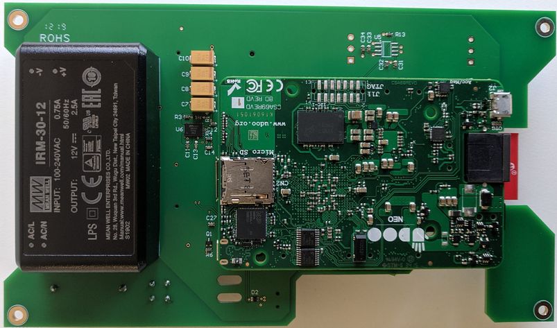
I have a PCB powered by an IRM-30-12 power supply (230VAC to 12VDC). On this PCB, I have a MRF24J40MD from Microchip and a Udooneo to drive it + a 5VDC regulator and the 3.3VDC of the Udooneo.

After installing over 300 units in different places, I noticed that some old fluorescent tubes are resetting the MRF24J40MD when someone switches the fluorescent tubes on or off. Replacing the old fluorescent tube with a new one make the trick and I have no more issue with the MRF24J40MD. But this takes lot of time.

My goal would be to design a protection circuit against this that I can plug or solder on the PCB on the 230VAC parts or 12VDC, 5VDC or 3.3VDC parts to protect my MRF24J40MD against resetting. Sadly, I have no idea how to manage this.

I could reproduce the bug at home with a Philips TMX 200 LS fluorescent tube and a Philips S10 starter. After some retries, the MRF24J40MD resets itself and doesn't communicate anymore if the PCB and the fluorescent tube are on the same plug.

EDIT: new measures with the oscilloscope following recommendations in the comments.

The 3.3VDC of the MRF24J40MD comes from the Udooneo. There's a separate power supply for the GSM parts.

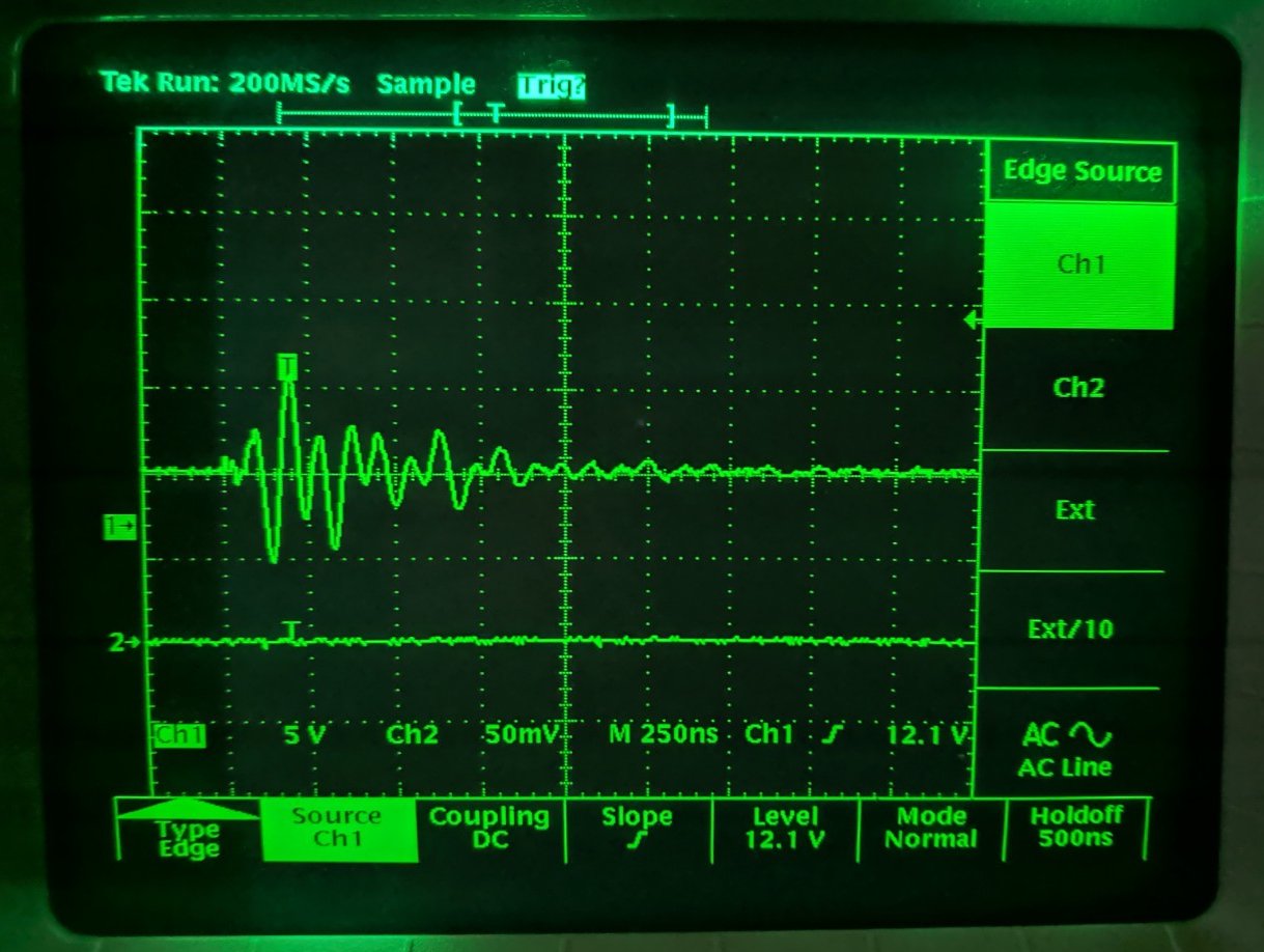
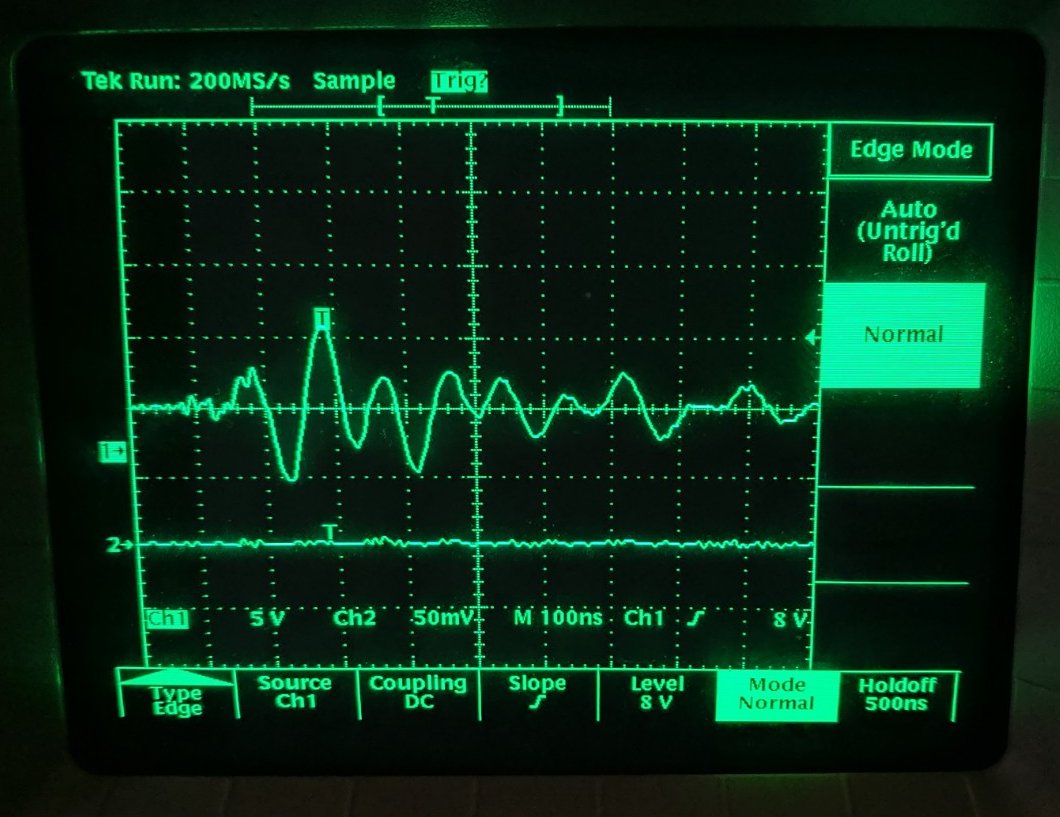
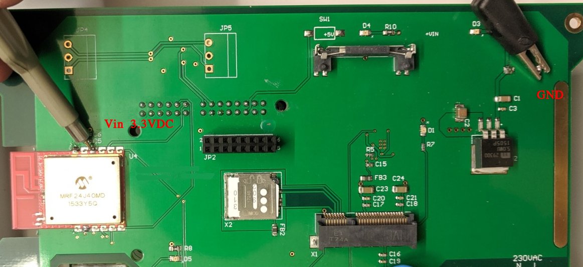
With an oscilloscope, I could mesure the perturbations at the 3.3VDC/GND of MRF24J40MD. I made the same measures on the output of main power supply (12VDC) and the perturbations are exactly the same. Here's the result on 3.3VDC/GND with new measurement setup (see below for probe setup):

Tube switched off 1 Tube switched off 2

The probe setup:

Probe Probe setup for measurements

The PCB (2 layers):

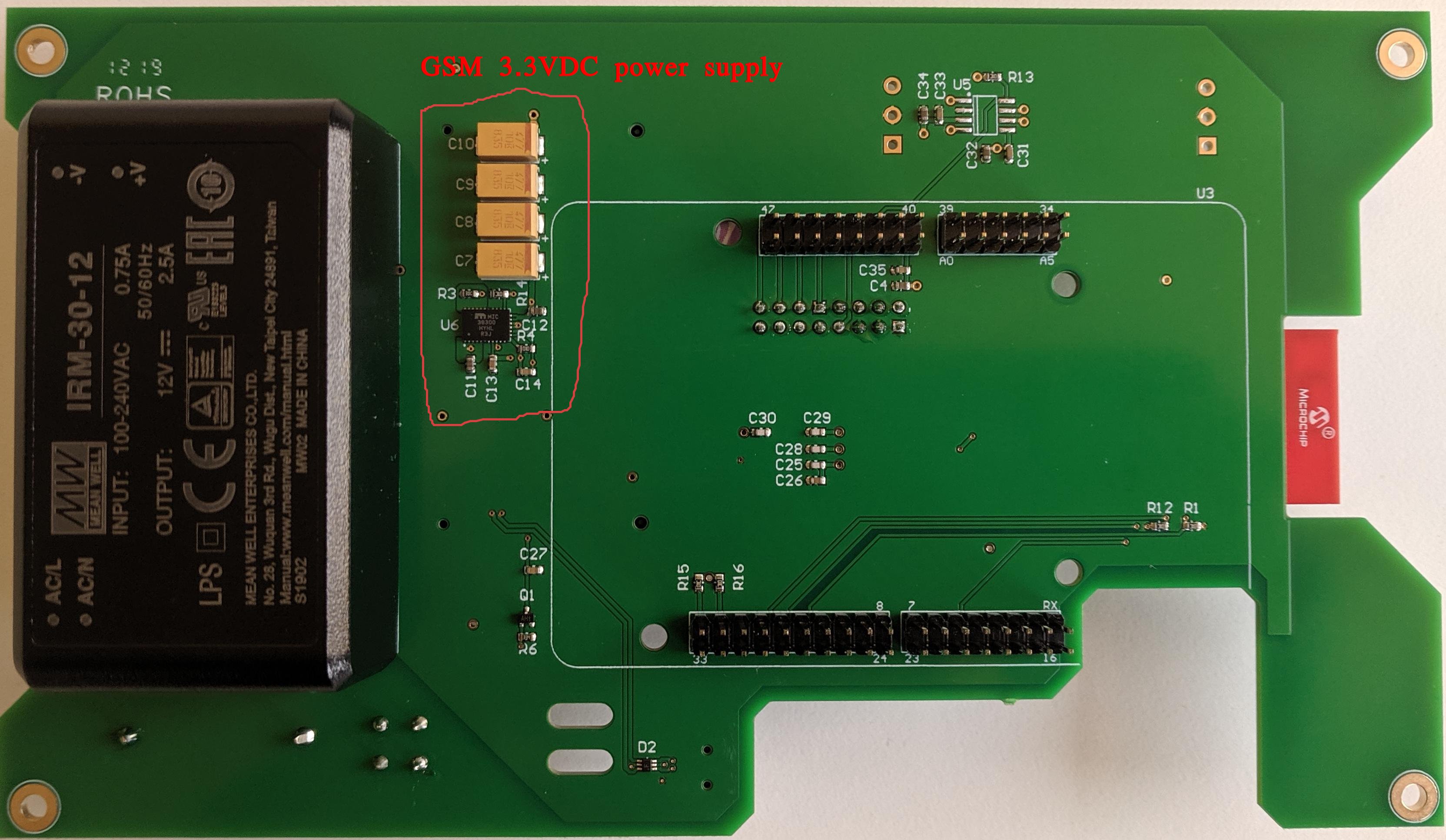
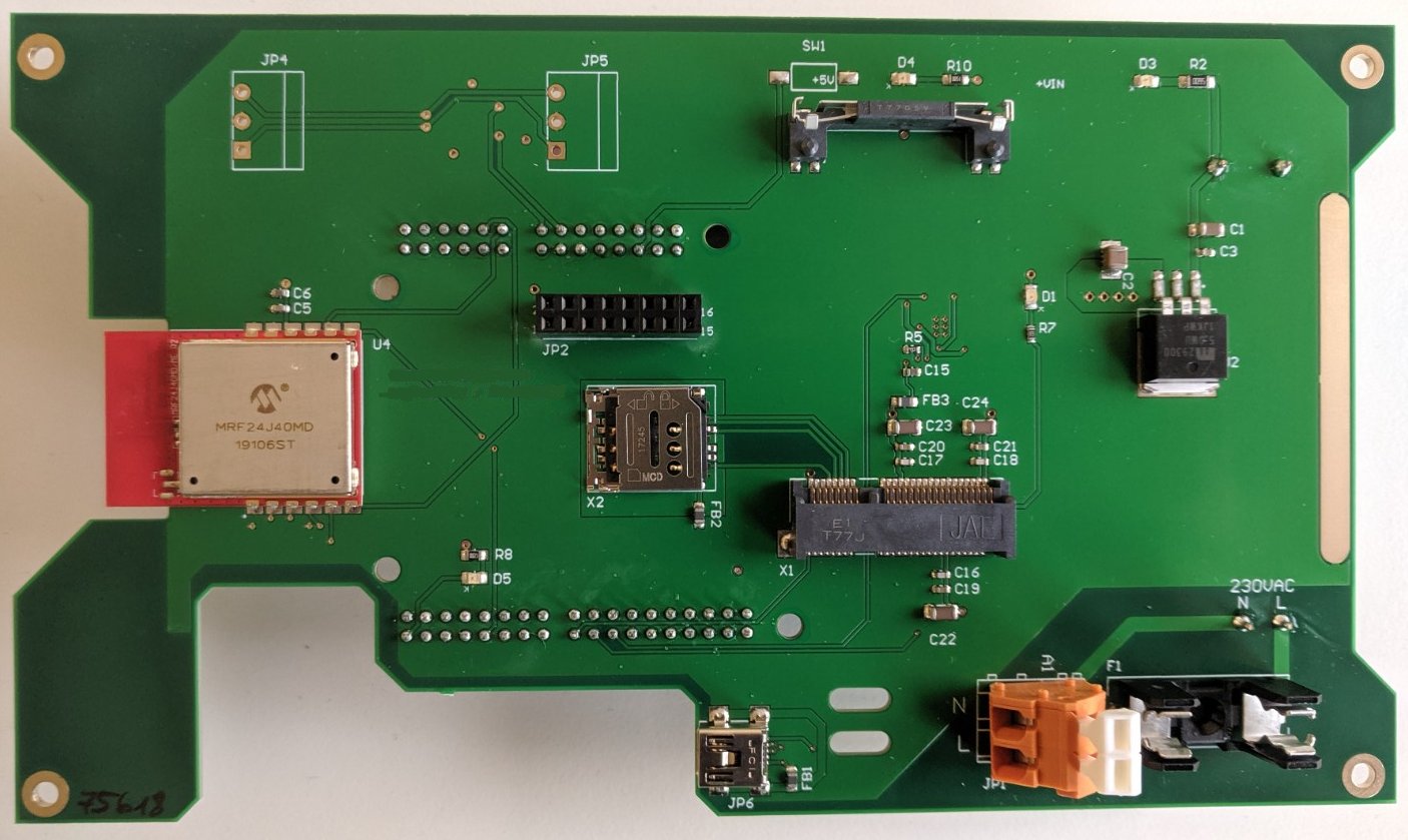
Bottom of PCB Bottom of PCB without Udooneo Top of PCB

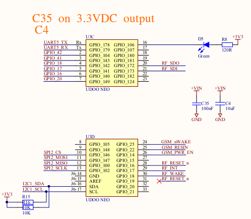
Some schematics (MRF24J40MD and 3.3VDC output of Udooneo):

3.3VDC output from Udooneo MRF24J40MD

Hope this isn't a too noob question and someone could suggest some ideas to help me solve this. For the little story, the PCB was designed by a group of junior engineers in a school. I'm a software engineer. That's why I'm struggling with this kind of problem and I can't reach the original designers anymore...
I have a PCB powered by an IRM-30-12 power supply (230VAC to 12VDC). On this PCB, I have a MRF24J40MD from Microchip and a Udooneo to drive it + a 5VDC regulator and the 3.3VDC of the Udooneo.

After installing over 300 units in different places, I noticed that some old fluorescent tubes are resetting the MRF24J40MD when someone switches the fluorescent tubes on or off. Replacing the old fluorescent tube with a new one make the trick and I have no more issue with the MRF24J40MD. But this takes lot of time.

My goal would be to design a protection circuit against this that I can plug or solder on the PCB on the 230VAC parts or 12VDC, 5VDC or 3.3VDC parts to protect my MRF24J40MD against resetting. Sadly, I have no idea how to manage this.

I could reproduce the bug at home with a Philips TMX 200 LS fluorescent tube and a Philips S10 starter. After some retries, the MRF24J40MD resets itself and doesn't communicate anymore if the PCB and the fluorescent tube are on the same plug.

EDIT: new measures with the oscilloscope following recommendations in the comments.

The 3.3VDC of the MRF24J40MD comes from the Udooneo. There's a separate power supply for the GSM parts.

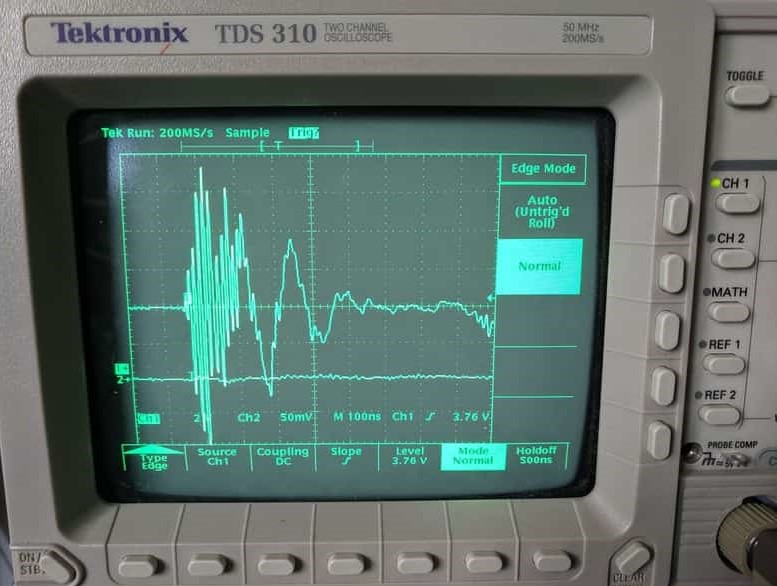
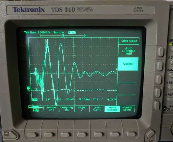
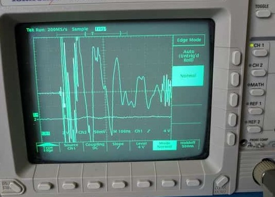
With an oscilloscope, I could mesure the perturbations at the 3.3VDC/GND of MRF24J40MD. I made the same measures on the output of main power supply (12VDC) and the perturbations are exactly the same. Here's the result on 3.3VDC/GND with new measurement setup (see below for probe setup):

Tube switched off 1 Tube switched off 2

The probe :

Probe

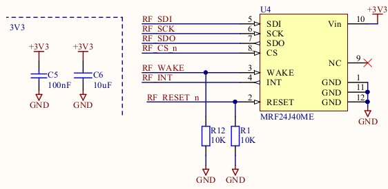
Some schematics (MRF24J40MD and 3.3VDC output of Udooneo):

3.3VDC output from Udooneo MRF24J40MD

Hope this isn't a too noob question and someone could suggest some ideas to help me solve this. For the little story, the PCB was designed by a group of junior engineers in a school. I'm a software engineer. That's why I'm struggling with this kind of problem and I can't reach the original designers anymore...

added 109 characters in body
Source Link
Carton_
  • 145
  • 8

I have a PCB powered by an IRM-30-12 power supply (230VAC to 12VDC). On this PCB, I have a MRF24J40MD from Microchip and a Udooneo to drive it + a 5VDC regulator and the 3.3VDC of the Udooneo.

After installing over 300 units in different places, I noticed that some old fluorescent tubes are resetting the MRF24J40MD when someone switches the fluorescent tubes on or off. Replacing the old fluorescent tube with a new one make the trick and I have no more issue with the MRF24J40MD. But this takes lot of time.

My goal would be to design a protection circuit against this that I can plug or solder on the PCB on the 230VAC parts or 12VDC, 5VDC or 3.3VDC parts to protect my MRF24J40MD against resetting. Sadly, I have no idea how to manage this.

I could reproduce the bug at home with a Philips TMX 200 LS fluorescent tube and a Philips S10 starter. After some retries, the MRF24J40MD resets itself and doesn't communicate anymore if the PCB and the fluorescent tube are on the same plug.

EDIT: new measures with the oscilloscope following recommendations in the comments. With

The 3.3VDC of the MRF24J40MD comes from the Udooneo. There's a separate power supply for the GSM parts.

With an oscilloscope, I could mesure the perturbations at the 3.3VDC/GND of MRF24J40MD. I made the same measures on the output of main power supply (12VDC) and the perturbations are exactly the same. Here's the result on 3.3VDC/GND with new measurement setup (see below for probe setup):

Tube switched off 1 Tube switched off 2

The probe setup:

Probe Probe setup for measurements

The PCB (2 layers):

Bottom of PCB Bottom of PCB without Udooneo Top of PCB

Some schematics (MRF24J40MD and 3.3VDC output of Udooneo):

3.3VDC output from Udooneo MRF24J40MD

Hope this isn't a too noob question and someone could suggest some ideas to help me solve this. For the little story, the PCB was designed by a group of junior engineers in a school. I'm a software engineer. That's why I'm struggling with this kind of problem and I can't reach the original designers anymore...
I have a PCB powered by an IRM-30-12 power supply (230VAC to 12VDC). On this PCB, I have a MRF24J40MD from Microchip and a Udooneo to drive it + a 5VDC regulator and the 3.3VDC of the Udooneo.

After installing over 300 units in different places, I noticed that some old fluorescent tubes are resetting the MRF24J40MD when someone switches the fluorescent tubes on or off. Replacing the old fluorescent tube with a new one make the trick and I have no more issue with the MRF24J40MD. But this takes lot of time.

My goal would be to design a protection circuit against this that I can plug or solder on the PCB on the 230VAC parts or 12VDC, 5VDC or 3.3VDC parts to protect my MRF24J40MD against resetting. Sadly, I have no idea how to manage this.

I could reproduce the bug at home with a Philips TMX 200 LS fluorescent tube and a Philips S10 starter. After some retries, the MRF24J40MD resets itself and doesn't communicate anymore if the PCB and the fluorescent tube are on the same plug.

EDIT: new measures with the oscilloscope following recommendations in the comments. With an oscilloscope, I could mesure the perturbations at the 3.3VDC/GND of MRF24J40MD. I made the same measures on the output of main power supply (12VDC) and the perturbations are exactly the same. Here's the result on 3.3VDC/GND with new measurement setup (see below for probe setup):

Tube switched off 1 Tube switched off 2

The probe setup:

Probe Probe setup for measurements

The PCB (2 layers):

Bottom of PCB Bottom of PCB without Udooneo Top of PCB

Some schematics (MRF24J40MD and 3.3VDC output of Udooneo):

3.3VDC output from Udooneo MRF24J40MD

Hope this isn't a too noob question and someone could suggest some ideas to help me solve this. For the little story, the PCB was designed by a group of junior engineers in a school. I'm a software engineer. That's why I'm struggling with this kind of problem and I can't reach the original designers anymore...
I have a PCB powered by an IRM-30-12 power supply (230VAC to 12VDC). On this PCB, I have a MRF24J40MD from Microchip and a Udooneo to drive it + a 5VDC regulator and the 3.3VDC of the Udooneo.

After installing over 300 units in different places, I noticed that some old fluorescent tubes are resetting the MRF24J40MD when someone switches the fluorescent tubes on or off. Replacing the old fluorescent tube with a new one make the trick and I have no more issue with the MRF24J40MD. But this takes lot of time.

My goal would be to design a protection circuit against this that I can plug or solder on the PCB on the 230VAC parts or 12VDC, 5VDC or 3.3VDC parts to protect my MRF24J40MD against resetting. Sadly, I have no idea how to manage this.

I could reproduce the bug at home with a Philips TMX 200 LS fluorescent tube and a Philips S10 starter. After some retries, the MRF24J40MD resets itself and doesn't communicate anymore if the PCB and the fluorescent tube are on the same plug.

EDIT: new measures with the oscilloscope following recommendations in the comments.

The 3.3VDC of the MRF24J40MD comes from the Udooneo. There's a separate power supply for the GSM parts.

With an oscilloscope, I could mesure the perturbations at the 3.3VDC/GND of MRF24J40MD. I made the same measures on the output of main power supply (12VDC) and the perturbations are exactly the same. Here's the result on 3.3VDC/GND with new measurement setup (see below for probe setup):

Tube switched off 1 Tube switched off 2

The probe setup:

Probe Probe setup for measurements

The PCB (2 layers):

Bottom of PCB Bottom of PCB without Udooneo Top of PCB

Some schematics (MRF24J40MD and 3.3VDC output of Udooneo):

3.3VDC output from Udooneo MRF24J40MD

Hope this isn't a too noob question and someone could suggest some ideas to help me solve this. For the little story, the PCB was designed by a group of junior engineers in a school. I'm a software engineer. That's why I'm struggling with this kind of problem and I can't reach the original designers anymore...
New pictures of : PCB + probe setup + schematics
Source Link
Carton_
  • 145
  • 8

I have a PCB powered by an IRM-30-12 power supply (230VAC to 12VDC). On this PCB, I have a MRF24J40MD from Microchip and a Raspberry PiUdooneo to drive it + a 5VDC regulator and the 3.3VDC of the Raspberry PiUdooneo.

After installing over 300 units in different places, I noticed that some old fluorescent tubes are resetting the MRF24J40MD when someone switches itthe fluorescent tubes on or off. Replacing the old fluorescent tube with a new one make the trick and I have no more issue with the MRF24J40MD. But this takes lot of time.

My goal would be to design a protection circuit against this that I can plug or solder on the PCB on the 230VAC parts or 12VDC, 5VDC or 3.3VDC parts to protect my MRF24J40MD against resetting. Sadly, I have no idea how to manage this.

I could reproduce the bug at home with a Philips TMX 200 LS fluorescent tube and a Philips S10 starter. After some retries, the MRF24J40MD resets itself and doesn't communicate anymore if the PCB and the fluorescent tube are on the same plug.

WithEDIT: new measures with the oscilloscope following recommendations in the comments. With an oscilloscope, I could mesure thisthe perturbations at the Vcc3.3VDC/GND of MRF24J40MD. I made the same measures on the output of main power supply (312VDC) and the perturbations are exactly the same. Here's the result on 3.3VDC/GND with new measurement setup (see below for probe setup):

Tube switched off 1 Tube switched off 2

The probe setup:

Probe Probe setup for measurements

The PCB (2 layers):

Tube switched offBottom of PCB Bottom of PCB without Udooneo Top of PCB

Tube switched off Some schematics (MRF24J40MD and 3.3VDC output of Udooneo):

Tube switched off3.3VDC output from Udooneo MRF24J40MD

Hope this isn't a too noob question and someone could suggest some ideas to help me solve this. For the little story, the PCB was designed by a group of junior engineers in a school. I'm a software engineer. That's why I'm struggling with this kind of problem and I can't reach the original designers anymore...
I have a PCB powered by an IRM-30-12 power supply (230VAC to 12VDC). On this PCB, I have a MRF24J40MD from Microchip and a Raspberry Pi to drive it + a 5VDC regulator and the 3.3VDC of the Raspberry Pi.

After installing over 300 units in different places, I noticed that some old fluorescent tubes are resetting the MRF24J40MD when someone switches it on or off. Replacing the old fluorescent tube with a new one make the trick and I have no more issue with the MRF24J40MD. But this takes lot of time.

My goal would be to design a protection circuit against this that I can plug or solder on the PCB on the 230VAC parts or 12VDC, 5VDC or 3.3VDC parts to protect my MRF24J40MD against resetting. Sadly, I have no idea how to manage this.

I could reproduce the bug at home with a Philips TMX 200 LS fluorescent tube and a Philips S10 starter. After some retries, the MRF24J40MD resets itself and doesn't communicate anymore if the PCB and the fluorescent tube are on the same plug.

With an oscilloscope, I could mesure this at the Vcc/GND of MRF24J40MD (3.3VDC) :

Tube switched off

Tube switched off

Tube switched off

Hope this isn't a too noob question and someone could suggest some ideas to help me solve this.

I have a PCB powered by an IRM-30-12 power supply (230VAC to 12VDC). On this PCB, I have a MRF24J40MD from Microchip and a Udooneo to drive it + a 5VDC regulator and the 3.3VDC of the Udooneo.

After installing over 300 units in different places, I noticed that some old fluorescent tubes are resetting the MRF24J40MD when someone switches the fluorescent tubes on or off. Replacing the old fluorescent tube with a new one make the trick and I have no more issue with the MRF24J40MD. But this takes lot of time.

My goal would be to design a protection circuit against this that I can plug or solder on the PCB on the 230VAC parts or 12VDC, 5VDC or 3.3VDC parts to protect my MRF24J40MD against resetting. Sadly, I have no idea how to manage this.

I could reproduce the bug at home with a Philips TMX 200 LS fluorescent tube and a Philips S10 starter. After some retries, the MRF24J40MD resets itself and doesn't communicate anymore if the PCB and the fluorescent tube are on the same plug.

EDIT: new measures with the oscilloscope following recommendations in the comments. With an oscilloscope, I could mesure the perturbations at the 3.3VDC/GND of MRF24J40MD. I made the same measures on the output of main power supply (12VDC) and the perturbations are exactly the same. Here's the result on 3.3VDC/GND with new measurement setup (see below for probe setup):

Tube switched off 1 Tube switched off 2

The probe setup:

Probe Probe setup for measurements

The PCB (2 layers):

Bottom of PCB Bottom of PCB without Udooneo Top of PCB

Some schematics (MRF24J40MD and 3.3VDC output of Udooneo):

3.3VDC output from Udooneo MRF24J40MD

Hope this isn't a too noob question and someone could suggest some ideas to help me solve this. For the little story, the PCB was designed by a group of junior engineers in a school. I'm a software engineer. That's why I'm struggling with this kind of problem and I can't reach the original designers anymore...
Tweeted twitter.com/StackElectronix/status/1128178368787222528
Source Link
Carton_
  • 145
  • 8
Loading