Tweeted twitter.com/StackElectronix/status/1086277222351003651
broken image fixed (click 'rendered output' to see the difference); for more info, see https://gist.github.com/Glorfindel83/9d954d34385d2ac2597bbe864466259f
Source Link

I have a hobby project that's been on the backburner for about 3 years now. It's very simple - just a solar-powered oscillator hooked up to a speaker, that changes frequency in response to the level of sunlight.

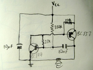
This is the circuit I'm using right now. It's mostly designed by Wilf Rigter from the BEAM circuits mailing list:

schematic http://frey.co.nz/content/images/solarchorus/solar_sounder_wilfs_improved_1_small.jpgschematic
The thing is I'd like to invert the frequency/sunlight response. At the moment in dark light it's a quiet tone with low frequency, and in bright light it's a loud tone with high frequency. Instead, I'd like to have a high-frequency tone in low light and a low-frequency tone/pulse train in bright light.

I'm really up against my knowledge limit in understanding this circuit as it is. What I do understand is that the 10nF capacitor charges through the 22k resistor until its voltage reaches the Vbe threshold for the NPN transistor on the bottom left, at which point the transistor opens and the capacitor discharges through the speaker, making a click. Then something happens to reset the system and it starts again. With more light the capacitor charges faster and so the tone has a higher pitch.

Inverting the frequency/light level response, though, is beyond me. I think I'd need to somehow slow down the charging of the timing capacitor here as the light increases by diverting the current somehow, and I suspect that I'd want to be storing this diverted current in another storage capacitor to be discharged through the speaker, instead of discharging the timing capacitor through the speaker. Actually building this into a schematic, though, is too difficult for me right now.

Any help much appreciated!

I have a hobby project that's been on the backburner for about 3 years now. It's very simple - just a solar-powered oscillator hooked up to a speaker, that changes frequency in response to the level of sunlight.

This is the circuit I'm using right now. It's mostly designed by Wilf Rigter from the BEAM circuits mailing list:

schematic http://frey.co.nz/content/images/solarchorus/solar_sounder_wilfs_improved_1_small.jpg

The thing is I'd like to invert the frequency/sunlight response. At the moment in dark light it's a quiet tone with low frequency, and in bright light it's a loud tone with high frequency. Instead, I'd like to have a high-frequency tone in low light and a low-frequency tone/pulse train in bright light.

I'm really up against my knowledge limit in understanding this circuit as it is. What I do understand is that the 10nF capacitor charges through the 22k resistor until its voltage reaches the Vbe threshold for the NPN transistor on the bottom left, at which point the transistor opens and the capacitor discharges through the speaker, making a click. Then something happens to reset the system and it starts again. With more light the capacitor charges faster and so the tone has a higher pitch.

Inverting the frequency/light level response, though, is beyond me. I think I'd need to somehow slow down the charging of the timing capacitor here as the light increases by diverting the current somehow, and I suspect that I'd want to be storing this diverted current in another storage capacitor to be discharged through the speaker, instead of discharging the timing capacitor through the speaker. Actually building this into a schematic, though, is too difficult for me right now.

Any help much appreciated!

I have a hobby project that's been on the backburner for about 3 years now. It's very simple - just a solar-powered oscillator hooked up to a speaker, that changes frequency in response to the level of sunlight.

This is the circuit I'm using right now. It's mostly designed by Wilf Rigter from the BEAM circuits mailing list:

schematic

The thing is I'd like to invert the frequency/sunlight response. At the moment in dark light it's a quiet tone with low frequency, and in bright light it's a loud tone with high frequency. Instead, I'd like to have a high-frequency tone in low light and a low-frequency tone/pulse train in bright light.

I'm really up against my knowledge limit in understanding this circuit as it is. What I do understand is that the 10nF capacitor charges through the 22k resistor until its voltage reaches the Vbe threshold for the NPN transistor on the bottom left, at which point the transistor opens and the capacitor discharges through the speaker, making a click. Then something happens to reset the system and it starts again. With more light the capacitor charges faster and so the tone has a higher pitch.

Inverting the frequency/light level response, though, is beyond me. I think I'd need to somehow slow down the charging of the timing capacitor here as the light increases by diverting the current somehow, and I suspect that I'd want to be storing this diverted current in another storage capacitor to be discharged through the speaker, instead of discharging the timing capacitor through the speaker. Actually building this into a schematic, though, is too difficult for me right now.

Any help much appreciated!

edited tags; edited title
Link
Toby Jaffey
  • 28.9k
  • 19
  • 98
  • 151

how How can iI invert a solar-powered oscillator's frequency?

Source Link
damian
damian

how can i invert a solar-powered oscillator's frequency?

I have a hobby project that's been on the backburner for about 3 years now. It's very simple - just a solar-powered oscillator hooked up to a speaker, that changes frequency in response to the level of sunlight.

This is the circuit I'm using right now. It's mostly designed by Wilf Rigter from the BEAM circuits mailing list:

schematic http://frey.co.nz/content/images/solarchorus/solar_sounder_wilfs_improved_1_small.jpg

The thing is I'd like to invert the frequency/sunlight response. At the moment in dark light it's a quiet tone with low frequency, and in bright light it's a loud tone with high frequency. Instead, I'd like to have a high-frequency tone in low light and a low-frequency tone/pulse train in bright light.

I'm really up against my knowledge limit in understanding this circuit as it is. What I do understand is that the 10nF capacitor charges through the 22k resistor until its voltage reaches the Vbe threshold for the NPN transistor on the bottom left, at which point the transistor opens and the capacitor discharges through the speaker, making a click. Then something happens to reset the system and it starts again. With more light the capacitor charges faster and so the tone has a higher pitch.

Inverting the frequency/light level response, though, is beyond me. I think I'd need to somehow slow down the charging of the timing capacitor here as the light increases by diverting the current somehow, and I suspect that I'd want to be storing this diverted current in another storage capacitor to be discharged through the speaker, instead of discharging the timing capacitor through the speaker. Actually building this into a schematic, though, is too difficult for me right now.

Any help much appreciated!