added 274 characters in body
Source Link
Mattman944
  • 17.4k
  • 1
  • 22
  • 50

The capacitance of the solderless breadboard may be causing your issues. This is a finicky circuit. The creators are proud that they can make this work with only a few parts, but real circuits have more parts for a reason, to make them work reliably.

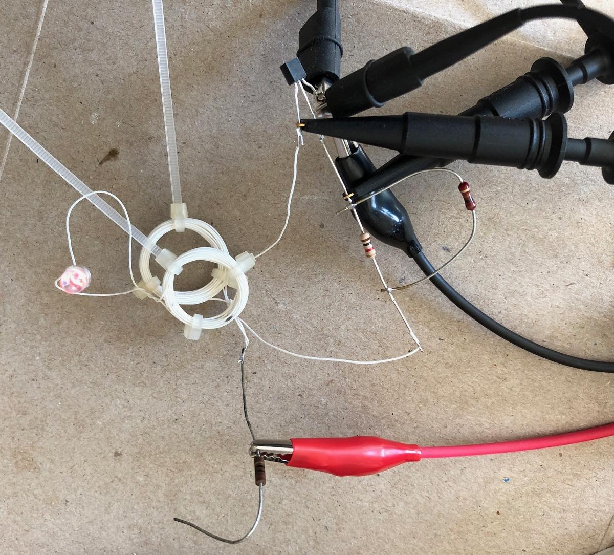
I was curious so I made the circuit. I used a BC546, basically the same as your transistor. My coil is 26 turns of 30 AWG solid wire, about 2 cm in diameter. I soldered the parts in mid-air. I started with a 1k base resistor. I set the current limit on my supply to 0.1 A, the rating of the transistor. It did not work. I lowered the base resistor to 100 ohms, it started working.

The supply current limits at 0.1A, ~1V!

The coils need to be within about 2 cm, with their axis (holes) aligned for the LED to light. Use a red, yellow, or orange LED since these have low voltage drops.

So, be sure that your coils are small. Don't use a solderless breadboard. Use a small PS voltage with the current limit set to 0.1A.

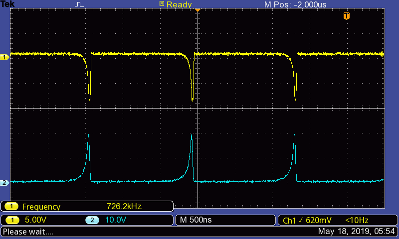
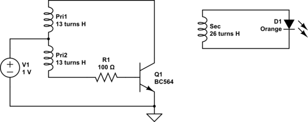
Channel 1 is the base voltage, channel 2 is the collector. Emitter is ground. The transistor is being stressed, the Vebo is being exceeded.
schematic

simulate this circuit – Schematic created using CircuitLab

enter image description here

enter image description here

The capacitance of the solderless breadboard may be causing your issues. This is a finicky circuit. The creators are proud that they can make this work with only a few parts, but real circuits have more parts for a reason, to make them work reliably.

I was curious so I made the circuit. I used a BC546, basically the same as your transistor. My coil is 26 turns of 30 AWG solid wire, about 2 cm in diameter. I soldered the parts in mid-air. I started with a 1k base resistor. I set the current limit on my supply to 0.1 A, the rating of the transistor. It did not work. I lowered the base resistor to 100 ohms, it started working.

The supply current limits at 0.1A, ~1V!

The coils need to be within about 2 cm, with their axis (holes) aligned for the LED to light. Use a red, yellow, or orange LED since these have low voltage drops.

So, be sure that your coils are small. Don't use a solderless breadboard. Use a small PS voltage with the current limit set to 0.1A.

Channel 1 is the base voltage, channel 2 is the collector. Emitter is ground. The transistor is being stressed, the Vebo is being exceeded.

enter image description here

enter image description here

The capacitance of the solderless breadboard may be causing your issues. This is a finicky circuit. The creators are proud that they can make this work with only a few parts, but real circuits have more parts for a reason, to make them work reliably.

I was curious so I made the circuit. I used a BC546, basically the same as your transistor. My coil is 26 turns of 30 AWG solid wire, about 2 cm in diameter. I soldered the parts in mid-air. I started with a 1k base resistor. I set the current limit on my supply to 0.1 A, the rating of the transistor. It did not work. I lowered the base resistor to 100 ohms, it started working.

The supply current limits at 0.1A, ~1V!

The coils need to be within about 2 cm, with their axis (holes) aligned for the LED to light. Use a red, yellow, or orange LED since these have low voltage drops.

So, be sure that your coils are small. Don't use a solderless breadboard. Use a small PS voltage with the current limit set to 0.1A.

Channel 1 is the base voltage, channel 2 is the collector. Emitter is ground. The transistor is being stressed, the Vebo is being exceeded.

schematic

simulate this circuit – Schematic created using CircuitLab
enter image description here

enter image description here

Source Link
Mattman944
  • 17.4k
  • 1
  • 22
  • 50

The capacitance of the solderless breadboard may be causing your issues. This is a finicky circuit. The creators are proud that they can make this work with only a few parts, but real circuits have more parts for a reason, to make them work reliably.

I was curious so I made the circuit. I used a BC546, basically the same as your transistor. My coil is 26 turns of 30 AWG solid wire, about 2 cm in diameter. I soldered the parts in mid-air. I started with a 1k base resistor. I set the current limit on my supply to 0.1 A, the rating of the transistor. It did not work. I lowered the base resistor to 100 ohms, it started working.

The supply current limits at 0.1A, ~1V!

The coils need to be within about 2 cm, with their axis (holes) aligned for the LED to light. Use a red, yellow, or orange LED since these have low voltage drops.

So, be sure that your coils are small. Don't use a solderless breadboard. Use a small PS voltage with the current limit set to 0.1A.

Channel 1 is the base voltage, channel 2 is the collector. Emitter is ground. The transistor is being stressed, the Vebo is being exceeded.

enter image description here

enter image description here